Intermatic 178GR10K-1 Manual


Læs gratis den danske manual til Intermatic 178GR10K-1 (10 sider) i kategorien Ikke kategoriseret. Denne vejledning er vurderet som hjælpsom af 37 personer og har en gennemsnitlig bedømmelse på 5.0 stjerner ud af 19 anmeldelser. Har du et spørgsmål om Intermatic 178GR10K-1, eller vil du spørge andre brugere om produktet?

Side 1/10
Spring Grove, Illinois 60081
www.intermatic.com
Thermistor Probe Kit
DDSX / DDFM Thermistor Probe Installation
SAFETY SECTION
WARNING – Risk of Fire or Electrical Shock
Disconnect the power at the circuit breaker(s) or disconnect the switch(es)
before installing or servicing.
More than one circuit breaker or disconnect switch may be required to
de-energize the equipment before servicing.
Installation and/or wiring must be in accordance with the national and local
electrical code requirements.
Use #18-14 AWG - COPPER conductors ONLY.
Keep the enclosure door closed at all times when not servicing, if applicable.
Replace the dead front after service or installation, if applicable.
Only use the Intermatic® Thermistor Probe Kit supplied for the DDSX or DDT40
models. The probe connection(s) to the DDSX control are NOT an isolated Class
2 circuit.
AVERTISSEMENT – Risque d’incendie ou de choc électrique
Utiliser des fils n° 18 à 14 AWG - Conducteurs en CUIVRE UNIQUEMENT.
NOTICE
Rotate the timer dial clockwise only, rotating counter-clockwise will damage the
timer within installed control.
Do not move the clock hands on the timer within installed control. Moving the
clock hands manually may damage the timer.
The thermistor wire may be extended up to 400 ft (122 m) using field-supplied
wiring between the DDSX control and the thermistor probe location.
This product is only intended to be used with the DDSX and DDT40 model series.
All trademarks are the property of their respective owners.
PRODUCT DESCRIPTION
The thermistor probe kit allows you to add additional probes to your existing adaptive defrost control. Up to four thermistor
probes may be added to monitor multiple evaporator coils. To order additional thermistor probe kits (for example, to connect
multiple evaporators to one control), use part number 178GR10K-1.
Thermistor Probe Contents Part Number 178GR10K-1
The kit includes:
One thermistor probe, with clip
One input lead
Four wire connectors
FIG. 1. Thermistor Probe Kit Contents
2
Thermistor Probe Kit
Specications
Environmental Ratings:
Operating temperature: -40° F to 130° F
(-40° C to 55° C)
Operating humidity: 0-95 RH % non-condensing
Thermistor Probe Ratings:
NTC thermistor with a resistance of 10 K Ω
Construction includes:
Protective copper sheath for good thermal
conductivity
Removable stainless steel retaining clip
#24 AWG wire leads with PVC insulation
Thermistor probe wire length: 10 ft (3.05 m)
Input lead length: 6 ft (1.83 m)
INSTALLATION
Tools Required
Needle nose pliers
Wire cutter
Wire stripper
Pre-Installation
1. Disconnect all power to the unit at the circuit breaker or
disconnect switch. You may need to disconnect more
than one circuit breaker or switch.
2. Plan the length of field-supplied copper wire needed
to connect the thermistor probe from the evaporator
coil to the input lead. (This wire may be up to 400 ft
(121.92m) long)
Note: The field-supplied wires may run along with the
power wires through existing or new conduit.
3. If present, open the enclosure door.
4. If present, remove the existing dead front cover. See
FIG. 2.
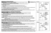
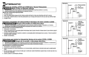
FIG. 2. Existing Dead Front
Install the Thermistor Probe
Note: Refer to WARNINGS on page 1 before
proceeding.
1. Connect the input lead to the CUBE™ module as I
shown in FIG. 3. The input lead may be inserted into
any of the four connectors on the CUBE™ module.I
FIG. 3. Attach the Input Lead


Produkt Specifikationer

Mærke: Intermatic
Kategori: Ikke kategoriseret
Model: 178GR10K-1

Har du brug for hjælp?

Hvis du har brug for hjælp til Intermatic 178GR10K-1 stil et spørgsmål nedenfor, og andre brugere vil svare dig