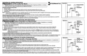
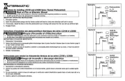
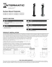
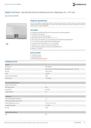
Intermatic ET8215C Manual


Læs gratis den danske manual til Intermatic ET8215C (4 sider) i kategorien Ikke kategoriseret. Denne vejledning er vurderet som hjælpsom af 15 personer og har en gennemsnitlig bedømmelse på 5.0 stjerner ud af 8 anmeldelser. Har du et spørgsmål om Intermatic ET8215C, eller vil du spørge andre brugere om produktet?

Side 1/4
Electronic Astronomic
7-Day Time Switch
Time Switch
Input Voltage: 120/208/240/277 VAC, 60 Hz
Power Consumption: 6.0 W Max.
Contact Conguration: SPST (ET8015C), DPST (ET8215C), and
SPDT (ET8115C). See wiring diagrams on next page.
Switch Ratings—ET8015C, ET8215C (per pole)
30 A Inductive/Resistive, 120/240 VAC, 60 Hz
20 A Ballast, 120-277 VAC, 60 Hz
20 A Resistive, 28 VDC
5 A Tungsten: 120/240 VAC, 60 Hz
1 HP, 120 VAC, 60 Hz
2 HP, 240 VAC, 60 Hz
Switch Ratings—ET8115C (NO/NC) Normally Open/Normally Closed Contact
20 A/10 A Inductive/Resistive, 120/208/240 VAC, 60 Hz
20 A/3 A Ballast, 120-277 VAC, 60 Hz
5 A Tungsten: 120/240 VAC, 60 Hz
1 HP / ¼ HP, 120 VAC, 60 Hz
2 HP / ½ HP, 240 VAC, 60 Hz
Set Points (Events)Each load output of the Time Switch can support up
to 14 timed ON and 14 timed OFF events per day as well as Astro ON
and Astro OFF events.
Installation and User Instructions
MODEL ET8000 Series
The Intermatic ET8000 Series Electronic Astronomic 7-Day Time
Switch automatically switches loads to a preset weekly schedule with
to-the-minute accuracy.
The astronomic feature provides an automatically adjusted sunset
ON and sunrise OFF to eliminate the need for separate photo control
devices.
The independent 7-day programming provides complete exibility for
applications where load switching differs each day of the week.
Astronomic programming can be combined with independent
programming to provide a sunset ON and timed OFF program.
Use the ET8000 series as an ON/OFF timer in applications requiring
7-day astronomic load control such as lighting, air conditioning systems,
pumps, etc. Each load output of the Time Switch can support up to 14
timed ON and 14 timed OFF events per day as well as Astro ON and Astro
OFF events. The program can be overridden by pushing the ON/OFF load
override button(s).
The ET8000 Series Time Switch is designed to directly switch tungsten
or ballast loads up to its rating, and inductive or resistive loads up to
30A at 120, 208, 240, or 277 VAC.
Specifications
With Battery
Carryover
Description
Front View Rear View
B
A
WARNING Risk of Fire or Electric Shock
• Disconnect power at the circuit breaker(s) or disconnect switch(es) before installing or servicing.
Installation and/or wiring must be in accordance with national and local electrical code
requirements.
For outdoor locations or wet locations (rain-tight), conduit hubs that comply with requirements of
the UL514B (standard fortting conduit and outlet boxes) are to be used.
This enclosure does not provide grounding between conduit connections. When metallic conduit
is used, you must also install grounding type bushings and jumper wire.
For plastic enclosures, bonding between conduit connections is not automatic and must be
provided as part of the installation.
• Use #18 - #10 AWG wires, rated at least 75°C - COPPER conductors ONLY.
If the power disconnect point is out of sight, lock it in the OFF position and tag it to prevent
unexpected application power.
Make sure there is no wire insulation under the terminal plate on the time switch connector.
Firmly tighten terminal screws.
• Do not remove insulator that is covering terminals.
• KEEP DOOR CLOSED AT ALL TIMES when not servicing.
NOTICE
Do NOT touch circuit board components, contact can create a static discharge, which can
damage the microprocessor.
Installation Instructions
Slide down
to remove
battery case
Snap out catch
Tilt top forward
2. Set voltage selector for desired input voltage. The timer is
shipped with voltage set for 120 VAC. To
operate at 208, 240 or 277 VAC, move the
selector switch to the desired setting as
marked on the circuit board. See location in A
Rear View above and detail at the right.
3. The timer is shipped with DST (Daylight Saving
Time) enabled. To disable DST, insert a jumper
at location marked DST. See location in BRear
View above and detail at the right.
4. ET8215C ONLYDecide whether you want to
control multiple loads simultaneously (SIM),
independently (IND), or with a 2-second pulse
(PUL) (e.g., for use with mechanically held
contactors or bell ringing applications), and
make sure the jumper is positioned accordingly.
See location in above and detail at the right. BRear View
(The unit is shipped with the loads set for IND.)
1. Remove the mecha-
nism from the case by
depressing the catch
at the top of the case
and pulling out, as
shown.
Battery-Powered Clock Operation3 years minimum (uses 2 AAA industrial
grade alkaline batteries, supplied)
Minimum ON or OFF time1 minute
Maximum ON or OFF time—6 days, 23 hours, 59 minutes
Shipping Weight2.5 lb. (1.1 kg)
EnclosuresThree enclosure options are available.
ET8xx5C – TYPE 1 indoor metal enclosure
ET8xx5CR – TYPE 3R indoor/outdoor lockable metal enclosure
ET8xx5CPD82 TYPE 3R indoor/outdoor lockable impact resistant
polycarbonate enclosure with clear cover
KnockoutsCombination 1/2-3/4 inch size, 1 on back and each side,
2 on bottom
Wire SizeAWG #18 through #10
Knockouts
Mounting holes
1
Neutral
120VAC
Input
Hot
2 3 4
Timer Power
Load
Install jumper
only if timer input
and load voltage
are the same
ET8015 configured for SPST, 120 VAC load
1
L2/N
120/208/240/277
VAC Input
Line 1
2 3 4 5 6
Load
1Load
2
Timer Power
Install jumper only if timer input
and load voltage are the same
ET8115 configured for SPDT load switching
1
Line 2
240VAC Input
Line 1
2 3 4 5 6
Line 1
Line 2
Install jumper only if timer input
and load voltage are the same
Timer Power
Load
ET8215 configured for 240 VAC DPST load
with jumper set to SIM
1
L2/N
120/208/240/277
VAC Input
Line 1
23456
ON
Install jumper only if timer input
and load voltage are the same OFF
Timer Power
ET8215 configured for pulse SPST load
with jumper set to PUL
1
L2/N
120/208/240/277
VAC Input
Line 1
2 3 4 5 6
Load
1
Timer Power
Load
2
ET8215 configured for 2 SPST loads
with jumper set to IND
1
L2/N
120/208/240/277
VAC Input
Line 1
2 3 4 5 6
Load
1
Timer Power
Load
2
ET8215 configured for DPST loads
with jumper set to SIM
Mounting
Holes
Knockouts
Mounting
Hole
Programming Overview
By pressing the button, the Time Switch will cycle through the MODE
menus necessary for programming the current time, date, astro zone,
astro events, and timed events.
The basic procedure is to use the button to move from one MODE
menu to the next (e.g., DATE, TIME, etc.), the or buttons for the +
rst part of a setting (e.g., MONTH), the button to move to the ENTER
next part of the setting (e.g., YEAR), then to exit and move to the MODE
next menu. To skip a menu, press to move ahead.MODE
If you make a mistake, press the button repeatedly to cycle MODE
back around to the error, then make the correct entry.
NOTE: DATE and TIME must be set before you can access any other
programming menus.
Setting Date
1. Press the button repeatedly until the words SET and DATE MODE
appear in the upper area of the display.
Setting Time
1. If necessary, press the button repeatedly until the words MODE
SET and CLOCK appear in the upper area of the display.
2. Press the or buttons to enter the current time.+
NOTE: To go from AM to PM, keep pressing the + or buttons to
cycle through the day. You can hold the buttons down for +or
3 seconds to make the time scroll quickly.
3. Press the button to exit and advance to setting Astro Zone.MODE
2. Press the or buttons to enter the current Month.+ –
3. Press the ENTER button when the Month is correct to save the
setting. The screen advances to current Date.
4. Again press the + or buttons to enter the current Date, followed
by the button.ENTER
5. Repeat to set the correct Year.
6. Press the button to exit and advance to setting the time.MODE
Wiring Diagrams
6. Replace the mechanism in the enclosure.
7. Lift the left side of the plastic insulator off the retaining post and
pivot it up and away to expose the terminal strip.
8. Strip the supply and load wires to 1/2”. Use #18 - #10
AWG wires, rated at least 75°C - COPPER conductors ONLY
5. Mount the enclosure in the desired location using the 3
mounting holes provided.
9. Insert the wire ends under the proper terminal plates (see wiring
diagrams elsewhere on this page) and tighten the screws rmly.
10. Connect ground wire to grounding terminal at bottom of enclosure.
11. Replace the plastic insulator on the retaining post.
12. Remove the battery case by sliding it down as shown by the
arrows, then install 2 AAA alkaline batteries. Make sure the
batteries are pointing in the direction shown.
13. Verify that the display is to make sure the batteries are OK.ON
If the display shows scrambled information, press the RESET
button to clear it up.
14. Apply power to the Time Switch.
The Time Switch is now ready for programming.
Position at eye level if possible, providing space to the left of
the enclosure for the cover to swing open fully, as shown.
IMPORTANT: ENTER Press and hold the button, then press the
RESET button. The screen will ash 12:00 AM and MON, and timer
status is Manual Mode.
NOTE: You must reset the time switch using this procedure
whenever you change the jumpers.


Produkt Specifikationer

Mærke: Intermatic
Kategori: Ikke kategoriseret
Model: ET8215C

Har du brug for hjælp?

Hvis du har brug for hjælp til Intermatic ET8215C stil et spørgsmål nedenfor, og andre brugere vil svare dig