Intermatic ET9250 Manual


Læs gratis den danske manual til Intermatic ET9250 (6 sider) i kategorien Ikke kategoriseret. Denne vejledning er vurderet som hjælpsom af 12 personer og har en gennemsnitlig bedømmelse på 4.3 stjerner ud af 6.5 anmeldelser. Har du et spørgsmål om Intermatic ET9250, eller vil du spørge andre brugere om produktet?

Side 1/6
ET9250 Relay Module Board
Relay Module Board Install, Upgrade and Replacement Instructions
MODEL ET9250
Disconnect power at the circuit breaker(s) or disconnect switch(es) before installing or servicing.
More than one disconnect switch may be required to de-energize the equipment before servicing.
Installation and/or wiring must be in accordance with national and local electrical code requirements.
Use #14 - #6 AWG wires, rated at least 90°C - COPPER conductors ONLY.
Use #14 - #8 AWG wires, rated at least 90°C - COPPER conductors ONLY. (ET90215C & ET90215CE ONLY)
KEEP DOOR CLOSED AT ALL TIMES when not servicing.
Some terminals in the ET90000-Series electronic timer may be energized even if the Status Screen is OFF. Check all terminals and wires with an appropriate
voltmeter before touching.
Make sure there is no wire insulation under the clamping plate and rmly tighten the terminal screws.
Keep low-voltage wiring separate from high-voltage wiring, including dead-front material between wiring areas. Use separate conduit for low-voltage wiring
with no line voltage circuits included.
WARNING Risk of Fire or Electric Shock
Deadfront Screws
Deadfront
Follow this procedure to replace a relay module board.
1. Disconnect power to the electronic control.
NOTE: more than one disconnect switch may be required to de-
energize the equipment before servicing.
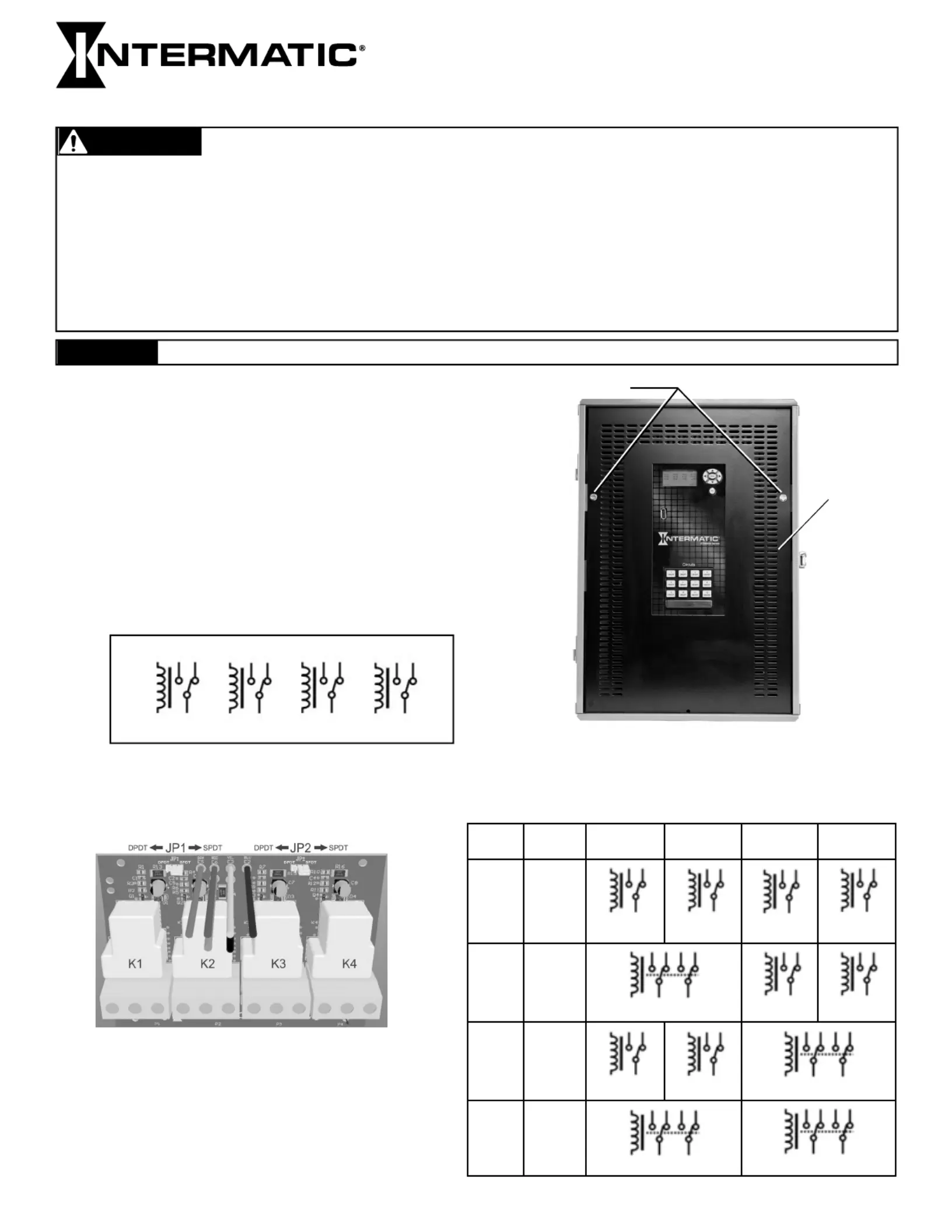
2. Open the time switch enclosure cabinet door.
3. Remove the screws on the deadfront and remove the
deadfront from the enclosure. (see Figure 1)
Set aside the deadfront and screws for reuse.
Figure 1. Removing the deadfront.
4. Remove the screw that secures the electronic control door
assembly and open the door assembly.
Set aside the screws for re-use.
5. The default output con guration of the new relay board
is set as four independently controlled SPDT relays (see
Figure 2).
6. By adjusting the two con guration jumpers on the board,
JP1 and JP2 (see Figure 3), the relays can be paired to
create different relay types as illustrated in the table below
(right).
SPDT SPDT SPDT SPDT
1 2 3 4
Figure 2.
Figure 3.
JP1 JP2 RELAY 1
(K1)
RELAY 2
(K2)
RELAY 3
(K3)
RELAY 4
(K4)
SPDT SPDT
DPDT SPDT
SPDT DPDT
DPDT DPDT
SPDT SPDT SPDT SPDT
DPDT SPDT SPDT
DPDT
SPDT SPDT
DPDT DPDT
NOTICE Do NOT touch circuit board components, contact can create a static discharge, which can damage these electronic components.
NOTE: When relays are paired, the even numbered relay
of the pair no longer appears on the display. For instance,
if the relay board is connected to act as outputs 5, 6, 7 and
8 with both jumpers set to DPDT then outputs 6 and 8 will
not show on the display. Outputs 6 and 8 would be
controlled from the schedule created for 5 and 7. Any
scheduled events programmed for outputs 6 and 8 would
also be ignored.
Different Relay Types
13. Select the position to install the new relay module board.
14. Remove the two screws opposite of the ller panel screws. Set aside the screws for installation.
15. Bend the ller at the serration line until it breaks and remove and discard the ller.
16. Remove the outer two screws that secure the ller panel on the new relay module board. Set aside the screws for
installation.
17. Insert the new relay board module onto the chosen position of the electronic control panel using the mounting holes
positioned over the holes from where the screws have been removed
18. Make sure there are no wires under the board. Secure the relay board to the mounting bracket with the previously
removed screws.
19. Connect the relay module cable connector plug to the applicable connector on the door assembly. Make sure the
plug latches.
20. Connect the circuit wires to the applicable connector plug on the relay board.
21. Close the door assembly and secure with the same screw that was removed.
22. Reinstall the deadfront and secure with the same screws that were removed
23. Close the enclosure cabinet door.
24. Apply power to the unit.
INTERMATIC INCORPORATED
SPRING GROVE, ILLINOIS 60081
www.intermatic.com
Figure 4. Removing the relay module board.
Terminal Connector
Timer Controller
Door Assembly
8. On the inside of the door assembly, remove the circuit wires from the applicable terminal connector(s) on the relay
board.
9. Disconnect the relay module cable connector plug from the applicable relay module connector on the door assembly.
See Figure 4 for location of the relay module cable connector plugs.
10. Remove the screws that secure the relay module board to the mounting bracket and remove the board.
Retain the screws.
11. Dispose of the old relay module board.
12. Go to step 17.
If you are... Then...
Replacing a Relay Module Go to step 8
Installing or updating a new Relay Module Go to step 13
LIMITED ONE-YEAR WARRANTY
If within the warranty period specified, this product fails due to a defect in material or workmanship, Intermatic Incorporated will repair or replace it, at its sole option, free of charge.
This warranty is extended to the original household purchaser only and is not transferable. This warranty does not apply to: (a) damage to units caused by accident, dropping or abuse
in handling, acts of God or any negligent use; (b) units which have been subject to unauthorized repair, opened, taken apart or otherwise modified; (c) units not used in accordance
with instructions; (d) damages exceeding the cost of the product; (e) sealed lamps and/or lamp bulbs, LEDs and batteries; (f) the finish on any portion of the product, such as surface
and/or weathering, as this is considered normal wear and tear; (g) transit damage, initial installation costs, removal costs, or reinstallation costs.
INTERMATIC INCORPORATED WILL NOT BE LIABLE FOR INCIDENTAL OR CONSEQUENTIAL DAMAGES. SOME STATES DO NOT ALLOW THE EXCLUSION OR LIMITATION OF
INCIDENTAL OR CONSEQUENTIAL DAMAGES, SO THE ABOVE LIMITATION OR EXCLUSION MAY NOT APPLY TO YOU. THIS WARRANTY IS IN LIEU OF ALL OTHER EXPRESS OR
IMPLIED WARRANTIES. ALL IMPLIED WARRANTIES, INCLUDING THE WARRANTY OF MERCHANTABILITY AND THE WARRANTY OF FITNESS FOR A PARTICULAR PURPOSE, ARE
HEREBY MODIFIED TO EXIST ONLY AS CONTAINED IN THIS LIMITED WARRANTY, AND SHALL BE OF THE SAME DURATION AS THE WARRANTY PERIOD STATED ABOVE. SOME
STATES DO NOT ALLOW LIMITATIONS ON THE DURATION OF AN IMPLIED WARRANTY, SO THE ABOVE LIMITATION MAY NOT APPLY TO YOU.
This warranty service is available by either (a) returning the product to the dealer from whom the unit was purchased or (b) completing a warranty claim online at www.intermatic.com. This warranty is
made by: Intermatic Incorporated, Customer Service 7777 Winn Rd., Spring Grove, Illinois 60081-9698. For warranty service go to: http://www.Intermatic.com or call 815-675-7000.
7. After adjusting the jumpers to t your output requirements take one of these actions:


Produkt Specifikationer

Mærke: Intermatic
Kategori: Ikke kategoriseret
Model: ET9250

Har du brug for hjælp?

Hvis du har brug for hjælp til Intermatic ET9250 stil et spørgsmål nedenfor, og andre brugere vil svare dig