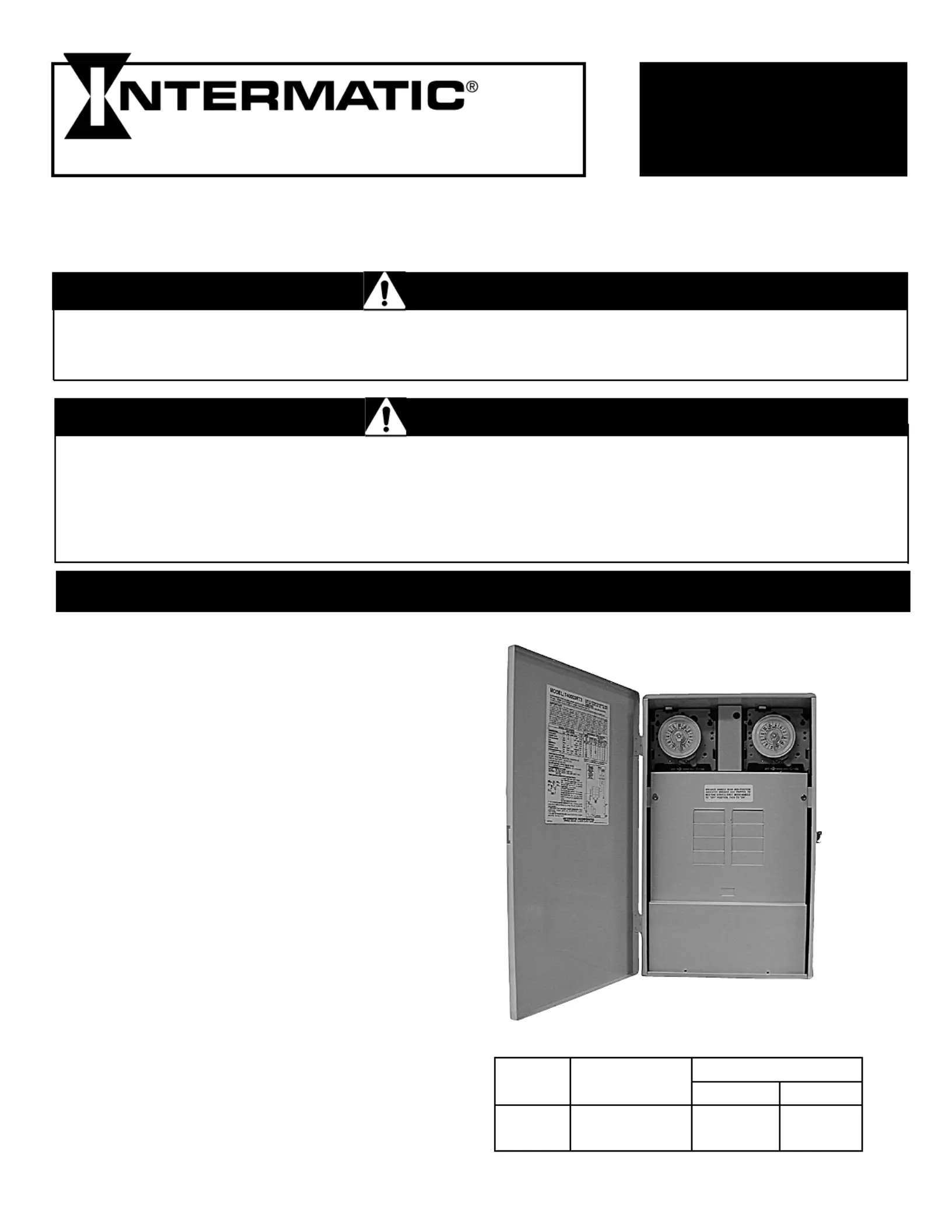
Intermatic T40000RT3 Manual


Læs gratis den danske manual til Intermatic T40000RT3 (4 sider) i kategorien Ikke kategoriseret. Denne vejledning er vurderet som hjælpsom af 11 personer og har en gennemsnitlig bedømmelse på 3.8 stjerner ud af 6 anmeldelser. Har du et spørgsmål om Intermatic T40000RT3, eller vil du spørge andre brugere om produktet?

Side 1/4
T40000RT SERIES
POOL/SPA EQUIPMENT CONTROLS
INSTALLATION
OPERATION &
SERVICE MANUAL
CONTROL PANEL WITH TIME SWITCH FOR INDOOR/OUTDOOR USE
Suitable for Pool Equipment Control and for Direct Connection of Underwater Lights
ELECTRICAL RATINGS: See inside Enclosure Door
Many of today’s energy efficient pools and spas
utilize the advantages of a single electrical panel,
containing all the necessary controls for the safe,
efficient and automatic operation of the pool/spa
equipment. In addition, this Panel can also be
used to control any outdoor equipment, sign or
pump within its rated capacity.
The Transformers supplied in these panels are
specifically designed to supply 12 volts to under-
water pool/spa lights. A grounded shield between
the primary and secondary winding assures safe
operation and the built-in circuit protection will
disconnect power to the transformer in case of
overload. These transformers are suitable for direct
connection to underwater Pool and Spa lights.
The all-weather enclosure may contain a heavy-
duty, industrial grade Time Switch, with
mounting provision for a second Intermatic
switching device. Also, it has provisions to install
a switch inside as well as a switch or GFCI
receptacle on the outside. The Time Switch can
also accommodate an optional heater control
(fireman) switch.
The Control is designed to operate any pump,
within its rated capacity. However, if protection
to prevent dry start is required by the pump
manufacturer, it must be provided in addition
to this Control. Contact pump manufacturer
if not sure and/or for more details. 1
GENERAL INFORMATION
Transformer Input Secondary Output
Rating 60 Hz. Lamp Watts* Volts
100W 120V. 1 Amp Max. 100 Max. 12, 13 or 14
300W 120V. 3 Amp Max. 300 Max. 12, 13 or 14
* Any combination of bulbs, any tap.
Risk of drowning!
Do not permit unsupervised children to use pool or spa.
Close supervision of children required at all times.
Risk of electric shock!
Test ground fault protection regularly. If it fails, do not use Pool or Spa. Contact
qualified service professional for help.
Do not use this control as a power disconnect, it could turn ON unexpectedly.
Disconnect electricity at the main Panel before servicing this control or the
equipment(s) connected to it.
DANGER
WARNING
INSTALLATION
1. Remove the four #10 hex head screws from the back
of the enclosure and attach mounting brackets to
enclosure.
2. Select the proper location for the Control Panel and
hang enclosure on a flat vertical surface or other
support, using hardware suitable for the purpose.
3. Prepare the necessary conduit runs, terminate
them at both ends and pull in the conductors as
specified by the installation layout.
4. Refer to Figure 1 below; note that
this enclosure contains one Time
Switch. To wire the panel, follow
the wiring diagram located inside
the enclosure door. Make sure that
connections to time switch terminals are tight
(25 lb.-in. )minimum and insulation clears the
pressure plate - see illustration.
5. If required by the heater manufacturer, install
fireman switch kit 156T4042A (not furnished)
on Time Switch Plate and make the fireman switch
connections. Use at least #18 AWG wiring with
insulation rated 300 Volt or higher. Place heater
ON/OFF switch on heater to ON (see Figure 2
on page 3). Some heaters may require a special con-
.necting harness, contact heater manufacturer for details
6. To install an additional wiring device inside the
enclosure, first remove rectangular knock-out(s) in
dead front. Next, remove hex head screws in back of
enclosure and install stand-offs* in place of screws.
Attach wiring device to stand-offs.
*Stand-offs are not furnished. Order 21T156A for a set of four
(4) stand-offs and mounting hardware.
7. If external bonding is required, install a bonding lug
at bottom of enclosure and bond installation
according to code requirements.
8. Testing of the installation is optional and
recommended only if pump is securely in place
and will not be damaged by this test:
a. Turn the manual lever of the Time Switch to OFF.
b. Turn ON power at breaker panel.
c. Move the manual lever of Time Switch to the
right (ON). Pump should start and run on full
speed. In case of unsatisfactory results, turn OFF
power, check your wiring, refer to Troubleshoot-
ing on Page 3.
2
Figure 1
9. The enclosure must be grounded as required by
NEC, Article 680 and any applicable local codes.
For Canadian installations, the transformer supply
circuit must be protected by a ground fault circuit
interrupter.
10. If this enclosure is used for direct connection of
underwater lights, refer to 1999 NEC 680-21(b),
2002 NEC 680-24(b) or CEC 68-060, 062 and 066
for further details.
11. Make sure that all unused transformer taps (leads)
are separately insulated.
12. Use the tables at the top of page 3 as a guide to
determine the correct wire size.
13. Check voltage at lamp terminals after installation.
It should be 12 0.3 volts. +
14. Install front panel over wiring compartment. The
control is now ready for programming, see
OPERATION section on Page 3.
Risk of injury or property damage!
Do not install or operate this equipment and other associated equipment without basic safety
precautions.
Read and follow the safety instructions listed below and other basic safety precautions before
installation or operation of this control and other associated equipment.
1. This control must be installed by a qualified person, according to the national and local electrical
codes.
2. Install this control not less than 5 feet (3 meters in Canada) from inside edge of pool and 1 foot
(30cm) above ground.
 3.USECOPPERCONDUCTORSONLYrated75˚Cminimum.
4. Do not exceed maximum ratings of individual components, wiring devices and current carrying
capacity of conductors.
5. For control grounding, bonding, installing and the wiring of underwater lights, refer to Article 680
of the National Electrical Code or Article 68 of the Canadian Electrical Code.
6. The control should not operate any equipment which would cause bodily injury or property
damage should it be activated unexpectedly.
CAUTION


Produkt Specifikationer

Mærke: Intermatic
Kategori: Ikke kategoriseret
Model: T40000RT3

Har du brug for hjælp?

Hvis du har brug for hjælp til Intermatic T40000RT3 stil et spørgsmål nedenfor, og andre brugere vil svare dig