JETI JMS-MSW Manual


Læs gratis den danske manual til JETI JMS-MSW (4 sider) i kategorien Radiostyret legetøj. Denne vejledning er vurderet som hjælpsom af 25 personer og har en gennemsnitlig bedømmelse på 5.0 stjerner ud af 13 anmeldelser. Har du et spørgsmål om JETI JMS-MSW, eller vil du spørge andre brugere om produktet?

Side 1/4
User manual: Magnetic switch
-1-
1. Introduction
The Magnetic switch is an electronic switching device designed to be used as a switch for JETI
model products. A big advantage of electronic switches in comparison to mechanical switches is that,
in general, electronic switches are highly resistant to vibration. Also, virtually an unlimited number
of ON and OFF cycles is guaranteed with an electronic switch. Because electronic switches have no
mechanically movable elements, contacts etc. to wear out, an extremely long service life is another
important feature. Unlike with mechanical switches, electronic switches cannot be unexpectedly or
falsely tripped.
The Magnetic switch’s trigger pad is designed for installation on an aircraft fuselage. The system is
switched on and off using a special magnet (see chapter 3).
2. Connection
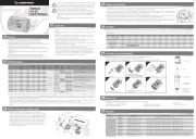
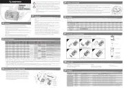
The Magnetic switch has 4 outputs that can be connected via three-wire cable with JR connector.
The outputs are divided into two pairs, one pair of outputs is electrically isolated (using an opto
coupler). Each pair of outputs has a single non-inverted output and a single inverted output.
ESC
Opto
User manual: Magnetic switch
-2-
Fig. 1: Magnetic switch application connections
Every individual device must be connected to the correct output from the Magnetic switch. If the
inverted output connection is confused for the non-inverted output, the switch will operate in reverse!
This means that the green LED on the magnetic switch will indicate the OFF state of the device!
If it is necessary to separate two circuits to prevent interference, be sure that the wiring is correct.
One circuit (the one where the interference is possible) must be connected to one of the switch
outputs that are optically isolated. The other circuit must be connected to one of the switch outputs
that are not optically isolated, see Fig. 1: Magnetic switch connections. When optical isolation is
desired, the –poles of the separated circuits must not be connected, as well as the + poles must not be
connected.
The Magnetic switch is powered from unseparated outputs, so at least one of these outputs must be
connected. If the power supply is interrupted when the magnetic switch is turned on, the devices
connected to optically isolated output are turned off! For example: in Fig 1, when power is
restored, the ignition would be turned off but the Rx would stay turned on.
3. The function of the Magnetic switch
The Magnetic switch is designed to switch the JETI model products on and off. For switching on,
the magnetic key must be placed on the small target in such a way that the small hole in the key and
the dot on the switch target has the same orientation. The Magnetic switch is equipped with a green
LED indicating the „switched on“ condition.


Produkt Specifikationer

Mærke: JETI
Kategori: Radiostyret legetøj
Model: JMS-MSW

Har du brug for hjælp?

Hvis du har brug for hjælp til JETI JMS-MSW stil et spørgsmål nedenfor, og andre brugere vil svare dig


Radiostyret legetøj JETI Manualer

JETI

JETI TD1609S Manual

21 August 2024
JETI

JETI JDEX-RR7 Manual

21 August 2024
JETI

JETI JEX-MF2G-800 Manual

21 August 2024
JETI

JETI JM-090-L Manual

20 August 2024
JETI

JETI TD0905L Manual

20 August 2024
JETI

JETI AddCAP 1640 Manual

20 August 2024

Radiostyret legetøj Manualer

Nyeste Radiostyret legetøj Manualer