GSM car alarm CA-1803BT „Athos“ 1/6 MHF56603
Installation manual: CA-1803BT “Athos” – mode 1
for cars without an original remote control for central locking
Main features for this mode:
Remote control of car central locking (if installed) via a remote
control.
Sending alarm and information SMS messages to up to 4
mobile phones.
Dialling pre-programmed phone numbers during alarms and
giving an acoustic warning signal.
Monitoring the vehicle‘s movement via GPS (Global
Positioning System).
Passing data to the central monitoring station.
Remote immobilization of the car via SMS instructions.
Remote control and programming of the alarm system from a
mobile phone.
Securing the vehicle’s goods area and the garage via up to 8
wireless detectors of the JA-8x series.
Handsfree calling from the car and remotely listening-in to the car
(receiving of any incoming calls and dialling up to 4 pre-
programmed phone numbers).
Extension of functions via the CR-11A module, for example,
operating an independent car appliance via SMS (12V only).
Internet access and configuration from the www.GSMLink.cz web
site.
1. Before installation
The auto-alarm should only be installed by a professional installer. It is
suitable for cars with a dashboard voltage supply of 12V or 24V with a
negative ground connection. During the first power-up, the value of supply
voltage is read and the inputs are set to default settings. The alarm is
designed to be installed inside the car.
The immobilizer relay contact of car alarm is connected only in disarmed
mode and if the ignition is on. Do not block circuits that are under voltage
while the ignition is off. It could cause a serious damage of the vehicle.
Disconnect the car battery before starting installation. For airbag-
equipped cars, no person is allowed to stay inside the car while handling
the battery. Disconnecting the battery can cause a reset of some of the
car’s devices (e.g. clock, default settings etc.). Avoid drilling into the metal
parts of the car body. The manufacturer is not responsible for damage
caused by any incorrect or unsuitable application of the product.
For crimping, special purpose tools should be used. If you do not use
some of the cables, cut them off at a distance of 10cm from the connector,
insulate them properly and tie them into a bunch.
For cars with a voltage supply of 24V, the following restrictions
apply to car alarm installation:
1. It is not possible to connect a hands-free set of type HF-03.
2. When used for acoustic signalling, the SIR output is switched to the
power supply voltage. Consequently, this output switches to 24V, so
it is necessary to use a siren of type SA-606-24V instead of the
siren which is supplied in the standard package. In this case it is
necessary to set the confirmation beeps to 100 ms.
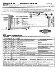
2. The wiring
Before installation, connect the wires as follows:
Yellow – output siren – switches to +12V (24 V) / max. 1.3 A. It
signals an alarm (30 sec) and confirms control signals
1.
Gray – door switch input. It reacts to connection or disconnection
from ground. These switches should be fitted to all of the car’s doors.
White – input INP1 – alarm input. It reacts to a connection or a
disconnection from the ground
Yellow-white – input INP2 – alarm input. It reacts to a connection or a
disconnection from the ground This input can trigger an alarm even if
disarmed (24 hour reaction).
Blue – signals that the ignition key is turned on. Reacts to +12V
(24V) from the switch case. Make sure that a voltage is present in the
connecting wire while starting.
Green – LED indicator – should be installed in a visible place on the
dashboard.
White-black (position 10) – “Lock”, White-blue (position 11) –
„Unlock“ – Central locking control outputs. They switch to ground
(max. 200mA) with a selectable pulse length. For MODE 1, a pair of
wires with black shrinkable tube should be put into the connector. The
wires are equipped with black isolation diodes which protect the
functionality of cars with an intelligent central unit.
Black – ground – connect to the original grounding point.
Red – power supply +12V (24V) - connect directly to the battery. The
power should be turned on only after a thorough check of the whole
installation has been made!
Orange – back-up battery – connects to a back-up battery of type BB-
02 (capacity 450 mAh, consumption up to 20 mA.)
2x Brown – immobilization circuit (max. 8A constantly, 12A
intermittently).
1 this function is optional
Pink – an optional function of the output, see table 7 – the output AUX –
power supply of external sensors is switched on by +12V/20mA or by bus
communication for modules CR-11A
It is possible to attach a hands-free set of type HF-03
2. Using this you are able
to phone out from the car via the car alarm, and also to remotely listen-in to the
car after an alarm has been triggered or after the car has been immobilized. The
HF set connects to the RJ connector on the front side of the car alarm unit.
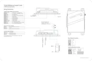
3. SIM card insertion
1. Make sure, that the PIN number on the SIM is disabled. If the SIM card
does not allow you to switch the PIN off, set the PIN to 0000. Remember
(note down) the phone number of your SIM card. It is recommended to
delete all original records in the SIM card’s phone directory.
2. Insertion of the SIM card: using a thin object, press the yellow peg in
order to pull out the SIM card holder (the front side of the alarm), insert the
SIM card into the casing with the conducting contacts facing up and push
the casing back carefully.
3. Install and attach the GSM antenna– (the car alarm must not be connected
to a power supply unless a GSM antenna is connected !!!). The antenna is
equipped with an adhesive tape and has to be stuck onto the car’s window or to
another suitable place like, for instance, below the upper part of the dashboard.
The antenna should not be installed close to the car alarm or near other
electronic devices. It is recommended to install the antenna in a place where it is
not easily visible (preferably in a tinted part of the window). Clear and dry the
spot carefully.
4. Install provided GPS antenna - place the antenna so that it will not be
shielded by metal parts of the car. It can be installed just under the top part of a
dashboard (turned with the black plastic cover upward) (the antenna can be
shielded by plastic materials). Wrap both connectors using plastic sticky tape as
they are connected to GND.
5. Check the wiring and connect the power supply. A flash of the indicator and
a beep of the siren indicate that the device is being connected to the GSM
network. Wait until the indicator turns off (up to 1 minute). After that the car
alarm is logged in to the GSM network.
If the flash does not disappear within 1 minute, it means that the login
process failed. If such a case occurs, turn off the power supply, pull out the
SIM card, ensure that the SIM contacts are clean, insert the card into a
mobile phone and check, whether a connection can be established in that
particular place. Also make sure that the SIM card‘s PIN is turned off (or that
it is set to 0000). If the mobile phone connection check is successful, return
the SIM card to the car alarm and repeat the whole procedure.
4. After turning the power supply on
In order to use the functionality of the car alarm according to your needs you first
have to setup its logic and behaviour by the RESET command. Subsequently,
phone numbers and other optional parameters should be set up and an RC-8x key
fob should be enrolled. The setup can be done in the following ways:
by editing a record in the SIM card phone directory (it is the simplest
setting method but limited to some functions only, see table 5.1). These settings
(which determine the devices‘ behaviour) are read from the SIM card after each
powering up of the car alarm. After the initial powering up of the new car alarm
with a new (blank) SIM card, configuration records (names) are created in the
SIM card’s phone directory and the default values set. But in the case that the
alarm had been set before and a new (blank) SIM card is then inserted, then the
stored parameters are copied from the internal memory to the SIM card. This
will help you after SIM card changing. You can perform basic settings of some of
the car alarm’s functions by pulling the SIM card out of the alarm (after the
power supply has been disconnected) and subsequently inserting it into a
mobile phone where you assign numbers to the names of functions displayed in
the phone directory from the SIM. See table 5.1 for setting the car alarm’s
optional parameters. Settings from the SIM card are read after its insertion and
powering up.
2
these accessories are optional