Kicker 50HDS962 Manual
Kicker
Ikke kategoriseret
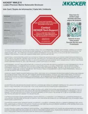
50HDS962

| Mærke: | Kicker |
| Kategori: | Ikke kategoriseret |
| Model: | 50HDS962 |
Har du brug for hjælp?
Hvis du har brug for hjælp til Kicker 50HDS962 stil et spørgsmål nedenfor, og andre brugere vil svare dig
Ikke kategoriseret Kicker Manualer

5 Februar 2025

5 Februar 2025
13 Januar 2025

2 September 2024

2 September 2024

2 September 2024

22 Februar 2024

28 Oktober 2022
Ikke kategoriseret Manualer
- Allen + Roth
- Livarno
- Suunto
- Xvive
- Twelve South
- Lescha
- Autotek
- AXTRA
- Dupla
- GreenPan
- Hozelock
- San Jamar
- Redmond
- E-ast
- Oscium
Nyeste Ikke kategoriseret Manualer

17 December 2025

17 December 2025

17 December 2025

17 December 2025

17 December 2025

17 December 2025

17 December 2025

17 December 2025

17 December 2025

17 December 2025