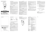
MODEL 8124/8125/8126/8127
KYORITSU ELECTRICAL INSTRUMENTS WORKS, LTD.,
This instrument has been designed, manufactured and
tested according to IEC
: Safety requirements for
ElectronicMeasuringapparatus,anddeliveredinthebest
condition after passing quality control tests. This
instruction manual containswarnings and safety rules
which have to be observed by the user to ensure safe
operationof the instrument andto maintain itin safe
condition. Therefore, read through these operating
instructionsbeforeusingtheinstrument.
Read through and understand instructions contained
inthismanualbeforeusingtheinstrument.
Keep the manual at hand to enable quick reference
The instrument is to be used only in its intended
Theoperating instructions described inthe manual
Understand and follow all the safety instructions
containedinthemanual.Itisessentialthattheabove
instructions are adhered to. Failure to follow the
aboveinstructionsmaycauseinjuryandorinstrument
damage. Kyoritsu is by no means liable for any
damageresultingfromtheinstrument incontradiction
indicated on the instrument, means that
theusermustrefertotherelatedpartsinthemanualfor
safeoperationoftheinstrument.Itisessentialtoreadthe
instructions wherever the
symbol appears in the
is reserved for conditions and actions
thatarelikelytocauseseriousorfatal
is reserved for conditions and actions
thatcancauseseriousorfatalInjury.
is reserved for conditions and actions
t h a t c a n c a u s e m i n o r i n j u r y o r
Never make measurement on a circuit in which
the electrical potential exceeds AC
Donot make measurement whenthunderrumbling.
If the instrument is in use, stop the measurement
immediately and remove the instrument from the
Donotattempttomakemeasurementinthepresence
of flammable gasses. Otherwise, the use of the
instrumentmaycausesparking,whichcanleadtoan
The transformer jaws are madeof metal and their
tips are not completely insulated. Be especially
careful about the possible shorting where the
measuredobjecthasexposedmetalparts.
Neverattempttousetheinstrumentifit
Do not exceed the maximum allowable input of any
Never attempt to make any measurement, if any
abnormalconditions are noted, suchas broken case,
Do n o t i n stall s ubsti t u t e p a rts o r m a k e an y
modification to the instrument. Return the instrument
to the distributor from who you purchased this
instrument for repair or re-calibration in case of
suspectedfaultyoperation.
Alwayskeepyourfingersandhandsbehindthebarrier
ontheinstrumenttoavoidthepossibleshockhazard.
Donotsteponorpinchthecordtopreventthejacket
ofcordfrombeingdamaged.
Theoutput connector shall beremoved orconnected
without clamping a conductor. Otherwise, it may
Do notexpose the instrument to direct sunlight,high
temperatures,humidityordew.
Never give shocks, such as vibration or drop, which
maydamagetheinstrument.
Use a damp cloth and detergent for cleaning the
instrument.Donotuseabrasivesorsolvents.
Refertotheinstructionsinthemanual.
Indicates a Instrument with double or reinforced
Indicatesthatthisinstrumentcanclamponbare
To ensure safe operation of measuring instruments, IEC
establishessafety standards for various electrical
environ-ments, categorized as O to CAT IV, and called
measurement categories. Higher-numbered categories
correspond to electrical environments with greater
momentaryenergy,soameasuringinstrumentdesignedfor
CATIIIenvironmentscanenduregreatermomentaryenergy
thanonedesignedforCATII.
O :Circuits which arenot directly connected to the
CATII :ElectricalcircuitsofequipmentconnectedtoanAC
electricaloutletbyapowercord.
CATIII:Primary electrical circuits of the equipment
connected directly to the distribution panel, and
feedersfromthedistributionpaneltooutlets.
CATIV:The circuit from the service drop to the service
entrance, and to the power meter and primary
overcurrentprotectiondevice(distributionpanel).
ThisisaclampsensorforourPowermeter.
Designed to international safety standard
CATIIIPollutionDegree
Barrier:It is a part providing protection against
electricalshockandensuringtheminimum
requiredairandcreepagedistances.
4. Din plug pin assignment
*Above figure shows the pin assignment seeing the
Clampsensorfromoutputconnectorpart. Thefigure
of the pin assignment of connection terminal is
symmetricaltoabovefigure.
6. Operating instructions
Never make measurement on a circuit in which the
electricalpotential exceeds AC
toavoidpossibleshockhazard.
The transformer jaws are made of metal and their tips
are not completely insulated. Be especially careful
aboutthepossibleshorting wherethemeasured object
Take sufficient care to avoid shock, vibration or
excessive force when handling the instrument.
Otherwise, precisely adjusted transformer jaws will be
When transformer jaws do not fully close, never try to
close them byforce, but make them free to move and
try again. If a foreign substance is stuck in the jaw
When making current measurements, keep the
transformerjawsfullyclosed.
Otherwise, accurate measurements cannot be taken.
Maximumconductorsizeisasfollows.
Hold the inserting part (except for the cable) and
disconnect the Outputconnector from the measuring
instrumentsoasnottocauseabreakinthecord.
)Connect the Output connector to the Input terminal of
themeasuringinstrument.
)Press the Trigger to open the transformer jaws and
clampontooneconductor.
Inthiscase,themeasuredconductorshallbeatthecenter
When connecting asensorwith a Power meter (our
, etc.) match the arrow
mark(Powersourcetoload), whichis indicatedonthe
transformer jaws, with the current flowing direction in
order tosynchronize the phases of measured current
)Ensure that the tips of transformer jaws are firmly
When using any of these sensors with KEW
,please refer to the instruction manual, eitherof
which you're using, and carefully check sensor type
settingsandavailablecurrentranges.
This instrument sat isfies the marking
requirement defined in the WEEE Directive
/EC). This symbol indicates separate
collection for electrical and electronic
Kyoritsu reserves the rights to change specifications or designs
describedinthismanualwithoutnoticeandwithoutobligations.
Temperature&humidityrange
%orless(nocondensation)
Operatingtemperaturerange
%orless(nocondensation)
Storagetemperaturerange
%orless(nocondensation)
Maximumpermissibleinput
Locationforuse Altitudeupto
EURoHSDirectivecompliant
betweenJawandenclosure
betweenenclosureandoutputterminal
betweenJawandoutputterminal
betweenJawandenclosure
betweenenclosureandoutputterminal
betweenJawandoutputterminal
betweenJawandenclosure
betweenenclosureandoutputterminal
betweenJawandoutputterminal
mmindiameter(max.) Approx.
Outputterminal MINIDIN
Accessories Instructionmanual