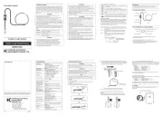
The following symbols are used and marked on the
instrument and in the instruction manual. Please carefully
check before starting to use the instrument.
Must refer to the Instruction Manual to protect humans
Instrument with double or reinforced insulation.
This instrument satisfies the marking requirement
defined in the WEEE Directive (2002/96/EC). This
symbol indicates separate collection for electrical and
● Never make measurement on a circuit in which the
earth potential exceeds 600V to avoid electrical
● Do not make measurement when thunder is rumbling.
If the instrument is in use, stop the measurement
immediately and remove the instrument from the
● Put insulated protective gears when there is a danger
of electrical shock hazard.
● Do not attempt to make measurement in the presence
of flammable gasses, fumes, vapor or dust. Otherwise,
the use of the instrument may cause sparking, which
can lead to an explosion.
● Never attempt to use the instrument if its surface or
● The instrument should be used only in its intended
applications or conditions. Otherwise, safety functions
equipped with the instrument do not work, and
instrument damage or serious personal injury may be
● Never attempt to make any measurement, if the
instrument has any structural abnormality such as
cracked case and exposed metal part.
● First, connect the Tester to Three-phase system and
then press the push switch button.
● If the cables are accidentally disconnected, release
your hand from the push switch button and stop
This instrument has been designed and tested according
to IEC Publication 61010: Safety Requirements for
Electronic Measuring Apparatus. This instruction manual
contains warnings and safety rules which must be
observed by the user to ensure safe operation of the
instrument and retain it in safe condition. Therefore, read
through these operating instructions before starting using
● Read through and understand instructions contained
in this manual before starting using the instrument.
● Save and keep the manual handy to enable quick
reference whenever necessary.
● The instrument is to be used only in its intended
● Understand and follow all the safety instructions
contained in the manual. Failure to follow the
instructions may cause injury, instrument damage
and/or damage to equipment under test. Kyoritsu is
by no means liable for any damage resulting from the
instrument in contradiction to this cautionary note.
indicated on the instrument means that
the user must refer to related parts in the manual for safe
operation of the instrument. Be sure to carefully read the
instructions following each symbol in this manual.
is reserved for conditions and actions that
are likely to cause serious or fatal injury.
is reserved for conditions and actions
that can cause serious or fatal injury.
is reserved for conditions and actions
that can cause minor injury or instrument
● Don't touch the disconnected cables while the push
switch button is being pressed down.
● Stop using the test lead if the outer jacket is damaged
and the inner metal or color jacket is exposed.
● Do not install substitute parts or make any modification
to the instrument. Return the instrument to Kyoritsu or
your distributor for repair or re-calibration.
● Even if all missing phase indicators are off, one phase
might be live: care should be taken to avoid getting
● Max continuous measurement time differs depending
on voltages. Please refer to continuous measurement
time written in this document and measure each
voltage within each limited time.
● Do not expose the instrument to the direct sun,
extreme temperatures or dew fall.
● Use a damp cloth and detergent for cleaning the
instrument. Do not use abrasives or solvents.
● This instrument isn't dust & water proofed. Keep away
● Choose and use the test leads and caps that are
suitable for the measurement category. When the
instrument and the test lead are combined and used
together, whichever lower category either of them
belongs to will be applied.
● Keep your fingers and hands behind the protective
fingerguard during measurement.
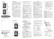
Measurement categories(Over-voltage categories)
To ensure safe operation of measuring instruments, IEC
61010 establishes safety standards for various electrical
environments, categorized as o to CAT IV, and called
measurement categories. Higher-numbered categories
correspond to electrical environments with greater
momentary energy. So a measuring instrument designed
for CAT III enviroments can endure greater momentary
energy than one desined for CAT II.
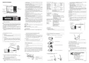
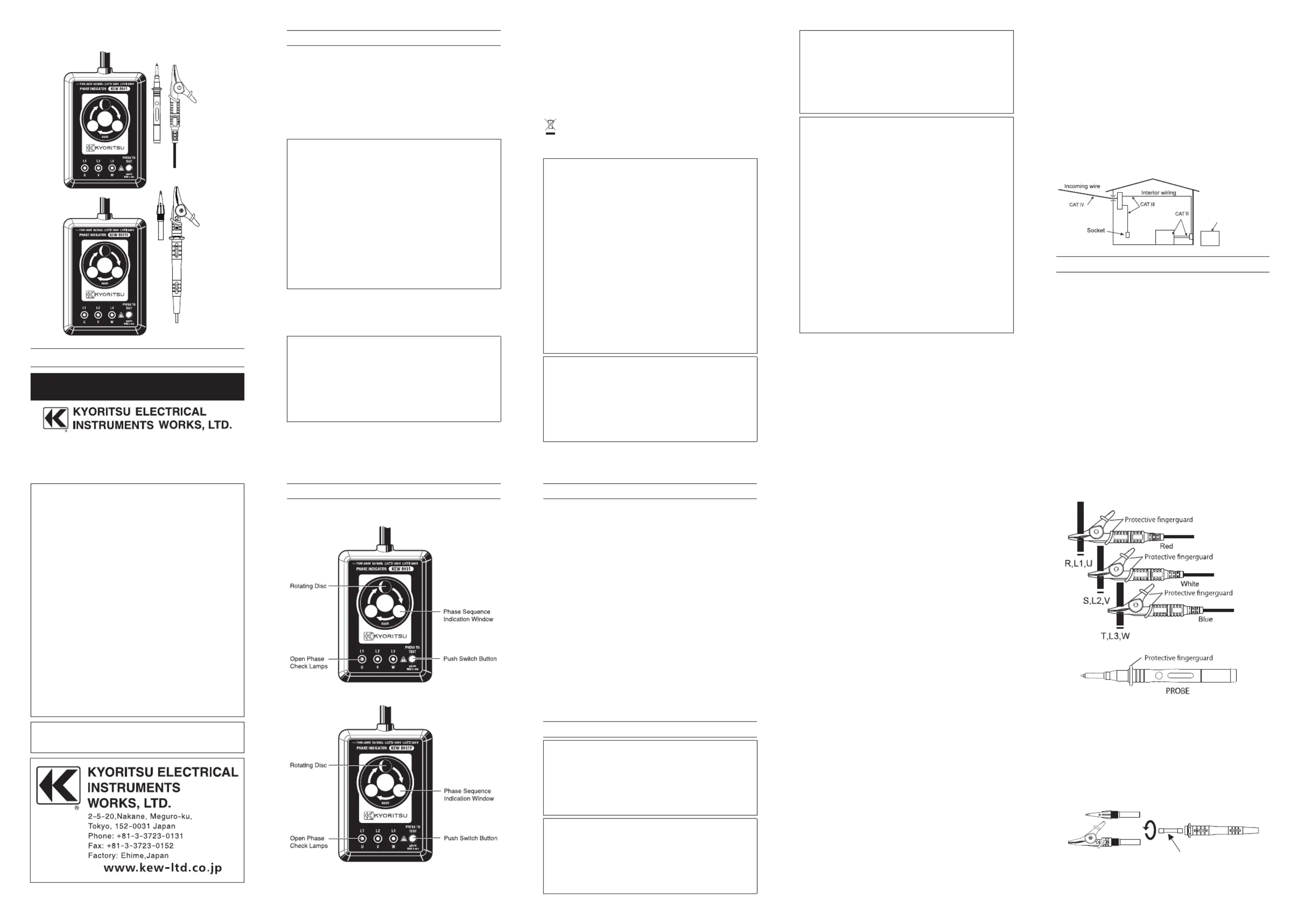
3. Instrument Layout 4. Specifications
Nominal system voltage Un( )
Continuous operation time
40 minutes or less from AC281V to AC300V
20 minutes or less from AC301V to AC400V
10 minutes or less from AC401V to AC500V
5 minutes or less from AC501V to AC600V
IEC 61010-1, IEC 61010-2-030
Measurement category CAT IV 300V,CAT III 600V
Standards : IEC 61326-1 (EMC), IEC 60529 (IP30)
Environmental standards : IEC 50581 (EU RoHS)
Altitude 2000m or less, Indoor use
AC6300V(rms) for 5seconds
106(L) x 75 (W) x 40 (D) mm (Body)
Fuse : 0.5A / 600V (F) 6.3X32mm (only KEW8031F)φ
5. Operating instructions
● First, connect the Tester to Three-phase system and
then press the push switch button.
● If the cables are accidentally disconnected, release
your hand from the push switch button and stop
● Don't touch the disconnected cables while the push
switch button is being pressed down.
● Even if all missing phase indicators are off, one phase
might be live: care should be taken to avoid getting
● Max continuous measurement time differs depending
on voltages. Please refer to continuous measurement
time written in this document and measure each
voltage within each limited time.
(1) Connect colour coded alligator clips or prods to the
terminals of a 3-phase power source where a rotating
electrical machine such as a motor will be connected or
(2) Press the push switch button located on top of the
unit. Keep this button pressed during phase sequence
or open phase check. When the push switch button is
released it immediately goes off.
(3) Make sure that all of the three lamps for phase check
are on. If so, there is no open phase. When any of the
three lamps is Not on there is open phase.
Open phase check Open phase on terminal→
Lamp "L1" is not on where Red alligator clip
Open phase check Open phase on terminal→
Lamp "L2" is not on where Whight alligator clip
Open phase check Open phase on terminal→
Lamp "L3" is not on where Blue alligator clip
※ When the open phase check lamps are not on the
rotating disc does not turn.
(4) Check the rotating direction of the inside disc through
the phase sequence indication window.
※ When the rotating disc turns counter-clockwise alternate
the connection of the two of the three alligator clips.
Then, the rotating disc will turn clockwise.
※ When the rotating disc turns clockwise phase sequence
isL1,L2 and L3 in order of the power source terminals
where the Red, Whight and Blue alligator clips are
Kyoritsu reserves the rights to change specifications
or designs described in this manual without notice and
O(None,Other):Circuits which are not directly
connected to the mains power
CATII:Primary electrical circuits of equipment
connected toanAC electrical outlet by
CATIII:Pr i m a r y e l e c t r i c a l ci r c u i t s o f the
equipment connected directly to the
distributionpanel,and feedersfromthe
distributionpaneltooutlets.
CATIV:The circuit from the serv ice drop
to the service entrance, and to the
power meter and primary overcurrent
protectiondevice(distributionpanel).
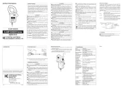
●TwoFunctionsinOneUnit
KEW8031 and KEW8031F is designed to
checkphasesequence. Lamps provided on
theunitwillalsotellyouifaphaseisopen.
Can check a wide range of 3-phase power
source from 110V to 600V. Sealed against
dust,theunitensurestrouble-freeperformance.
Small, Lightweight and portable.Designed for
maximumeaseofoperationandruggedness.
No exposed metal parts. Safety features are
incorporatedincludingtheinstantpushbutton
※When the instrument and the test lead are combined and
used together, wh hever lower category either of themic
belongs to w l be app ed.il li
How to replace the fuse ( W8031F)KE
Turn the probe to sp t itli
It is a part providing protection
against electrical shock and
ensuring the minimum required
air and creepage distances.