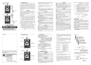
POWER CLAMP SENSOR Series
This clamp sensor has been designed and tested according to IEC61010-1:
Safety Requirements for Electronic Measuring Apparatus, and delivered in the
best condition after passing quality control tests. This instruction manual
contains warnings and safety rules which have to be observed by the user to
ensure safe operation of the clamp sensor and to maintain it in safe condition.
Therefore, read through these operating instructions before starting to use the
● Read through and understand instructions contained in this manual
before starting to use the clamp sensor.
● Keep the manual at hand to enable quick reference whenever necessary.
● The clamp sensor is to be used only in its intended applications.
● Understand and follow all the safety instructions contained in the manual.
It is essential that the above instructions are adhered to. Failure to follow the
above instructions may cause injury, clamp sensor damage and/or damage to
equipment under test. KYORITSU is not liable for any damage resulting from
the mishandling of the clamp sensor.
The symbol indicated on the clamp sensor, means that the user must refer
to the related parts in the manual for safe operation of the clamp sensor. It is
essential to read the instructions wherever the symbol appears in the
is reserved for conditions and actions that are likely to
cause serious or fatal injury.
is reserved for conditions and actions that can cause
: is reserved for conditions and actions that can cause injury
● Do not make measurements on a circuit in which electrical potentials
exceeding the following values exist: 300 higher V or in CAT IV
environment and or higher or lower600 V in CAT III environment.
● Use the sensor only as specified rotection supplied by ; otherwise, the p
the sensor can be compromised and damage itself or lead to a serious
accident. Always verify the proper operation on a well known power -
source before starting to use the sensor.
● Stop using the sensor if any visible damage such as cracks on the circuit
box or clamp part, or exposed internal metal parts are found.
● Do not disassemble, install substitute parts or make any modification to the
clamp sensor. Return the clamp sensor to your local KYORITSU distributor
for repair or re calibration in case of suspected faulty operation.-
● Do not use the clamp sensor if the sensor or your hand is wet; otherwise,
electrical shock accident may occur.
● Comply with the local and national safety code use the protective gears s and
● Do not step on or pinch the cord; it may damage the jacket of the cable.
● Do not expose the clamp sensor to direct sunlight, high temperature,
humidity or dew. deformation or insulation degradation and It may cause
cannot meet the original specification.
● Not to give shocks, such as vibration or drop, which may damage the
clamp sensor, during transit or use.
● Use a damp cloth with water or neutral detergent for cleaning the clamp
sensor. Do not use abrasives or solvents.
● This clamp sensor is not designed to be dust or waterproof. Do not use it
dusty places or where the clamp sensor is likely to be wet. It can damage
● Never pinch foreign matters or give vibrations to the joint part of the
clamp sensor: otherwise, the joint part may be damaged and lead to
● Do not bend or pull the root of the cable to prevent breaks in the cable.
● Never apply a current exceeding the measuring range for a long time.
It may damage the clamp sensor.
● Do not connect/remove the connectors while connected devices are the
on or clamping onto the conductor under test. Otherwise, the connected
device or clamp sensor may be damaged.
● Accurate measurement may not be obtained in the vicinity of strong magnetic
-fields such as transformers, high current circuits or wireless machines.
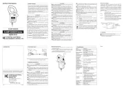
Meaning of symbols on the clamp sensor:
User must refer to the explanations in the instruction manual for
Clamp sensor with double or reinforced insulation
Do not use for, attach to or detach from insulated hazardous live un-
conductors, which may render electric shock, electric burn, or arc
Crossed-out wheel bin symbol (according to WEEE Directive: 2002/
96/ EC) indicating that this electrical product may not be treated as
household waste, but that it must be collected and treated separately.
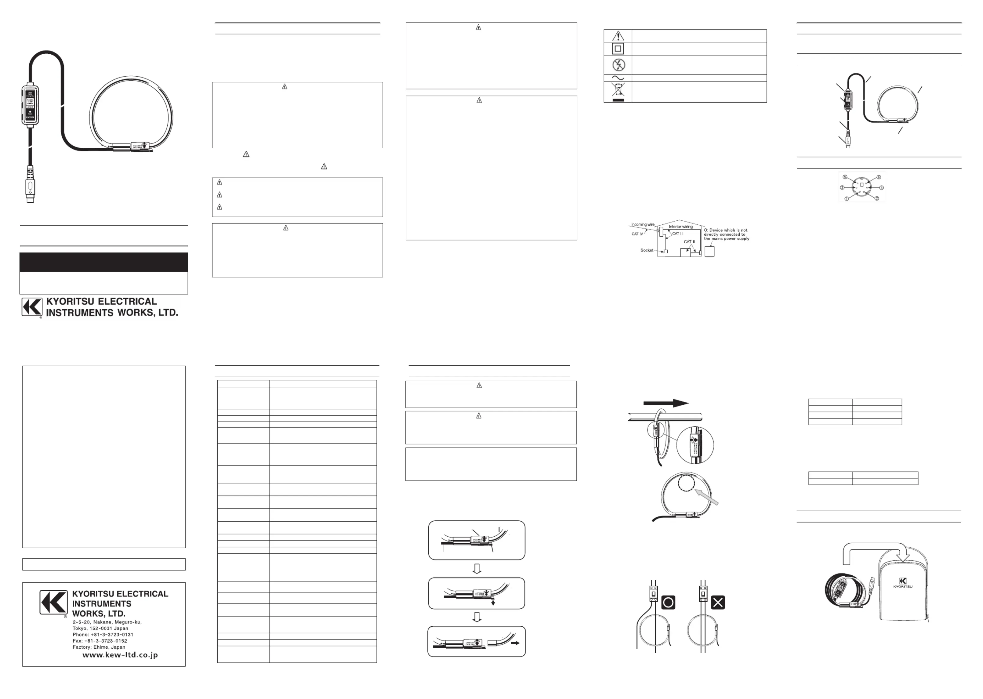
To ensure safe operation of measuring instruments, IEC 61010 establishes
safety standards for various electrical environments, categorized as O to CAT
IV, and called measurement categories. Higher numbered categories -
correspond to electrical environments with greater momentary energy, so a
measuring instrument designed for CAT III environments can endure greater
momentary energy than one designed for CAT II.
: Circuits which are not directly connected to the mains power supply.
CAT II : Electrical circuits of equipment connected to an AC electrical outlet
CAT III : Primary electrical circuits of the equipment connected directly to
the distribution panel, and feeders from the distribution panel to
CAT IV : The circuit from the service drop to the service entrance, and to
the power meter and primary over current protection device -
● This is a clamp ensor s which can measure AC current up to 50 A.
● Flexible and lightweight is achieved by using air core coil for the ensors .
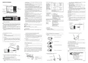
4. Pin assignment for output terminal
* Pin assignment at the connecting terminal of measuring instrument is
symmetrical to above figure.
● Output signal passes between
● This clamp sensor drives power via the output cable. Power supply of +3.0
to +5.5V is required between
-of output terminal and 3.0 to
- 5.5V is required between
Sensor identification (91 kΩ)
KEW 6315/ 6315WHM Power Quality Analyzer
KEW 5010 Logger (for current)
KEW 5020 Logger (for current & voltage)
500 mV AC/ 50 A AC ( 10 mV/ A)
0 – 50 A A P AC rms (92 eak)
±1.0%rdg±0.5 0 – (mV (45 65 Hz) – 50 A)
±1.5%rdg±0.5 – 0 mV (40 300 Hz) ( – 20 A)
±1.5%rdg±0.5 – 1 ( – 5 A)mV (300 kHz) 0
±1.0%rdg±0.5mV (45 – Hz 65 Hz)
Relative humidity or less (no condensation)85%
Relative humidity or less (no condensation)85%
Relative humidity or less (no condensation)85%
Altitude up to 2000 m -, In door use
CAT III (600 V ), CAT IV (300 V ),
5160 V AC sec. rms (50/ 60 Hz)/ 5
Between circuit and clamp sensor
Between circuit and clamp sensor
Approx. 2.7 m: between circuit box and clamp sensor
Approx. 0.2 m: between circuit box and output
C arrying bag (MODEL9095)
C - 4 ( ) able marker No.1 No. 2pcs each
6. Operating instructions
● Never make measurements on a circuit in which electrical potentials
exceeding the following values exist: or higher CAT IV and 600300 V in V or
higher in CAT III or lower environment.
● The measurable conductor size is n diameter Make sure that 75 mm i (max).
the clamp sensor is firmly closed for accurate measurement.
● When disconnecting the output terminal from the measuring instrument, do
so by removing the plug and not by pulling the cable.
● This sensor has been specially designed and dedicated to our Power meter
KEW 6305, Power quality analyzer KEW / 6315WHM, and Logger 6315
KEW 5010/ 5020. It cannot be used with the other our products such as
(1) Connect the output terminal to the input terminal on the measuring
(2) Power on the measuring instrument.
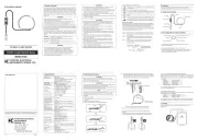
(3) Unlock the Joint according to the following illustrations.
(4) Clamp onto one conductor to be tested. Locate the conductor as shown
below while observing e direction of the uide arrow mark indicating the th G -
current flowing direction - marked on the Joint of the sensor to synchronize
the phases of the current under test and output voltage.of the
(5) Ensure that the joint part of the clamp sensor is firmly locked.
● Joint part may be unlocked and disconnected if excessive force is
● Clamp onto just one conductor measurements cannot be made when ;
clamping single- - - -phase (2 wire) or three phase (3 wire) at the same time.
Position the conductor to be tested as illustrated above.
6-2 Connecting with KEW 063 5/KEW 5631 / KEW 6315WHM
Before connecting sensor with this KEW 6305 or KEW 6315, confirm that the
internal firmware version is later than the one listed in the following table;
otherwise, this sensor cannot be used . The latest firmware is available on with
For the detailed setting of the clamp sensor, please refer to the instruction s
manual for the applicable model.
6-3 Compatiblility with KEW 6305
When using this sensor with KEW 6305, confirmm the serial no. of the tester is
later than that is listed in below table.
If your KEW 6305 has a former serial no. than the one listed above, accuracy
isn’t guaranteed when two or more KEW 8135 are connected with KEW 6305.
Organize the cable sensor as shown below and in theand the store them
Kyoritsu reserves the rights to change specifications or designs
describedinthismanualwithoutnoticeandwithoutobligations.