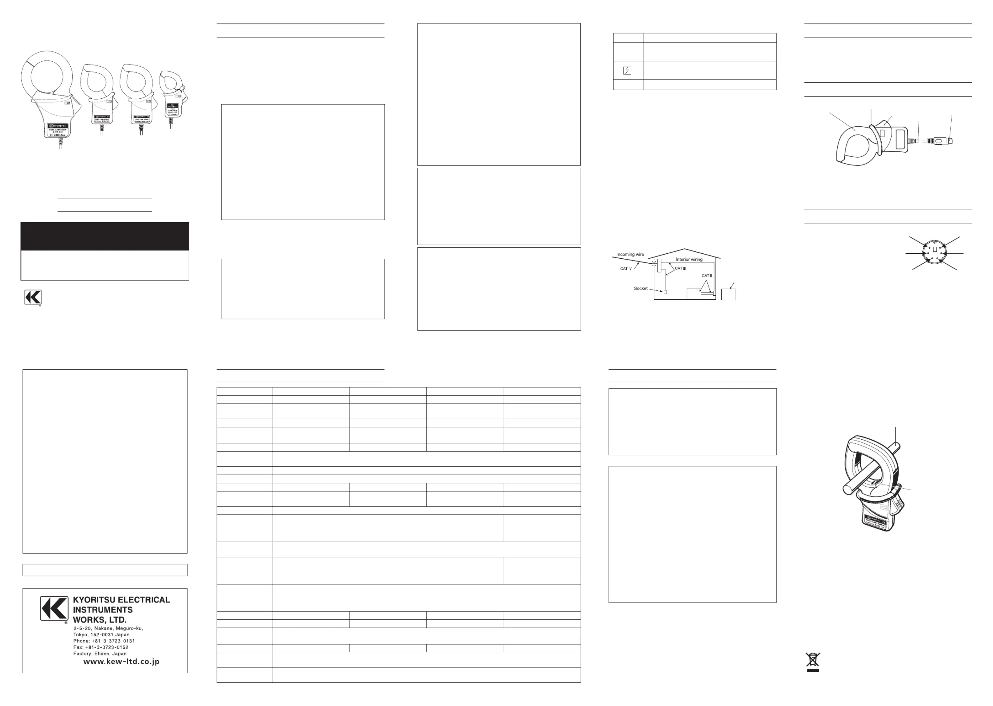
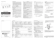
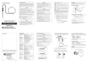
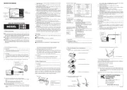
Kyoritsu 8127 Manual


Læs gratis den danske manual til Kyoritsu 8127 (1 sider) i kategorien Måling. Denne vejledning er vurderet som hjælpsom af 9 personer og har en gennemsnitlig bedømmelse på 4.5 stjerner ud af 5 anmeldelser. Har du et spørgsmål om Kyoritsu 8127, eller vil du spørge andre brugere om produktet?

Side 1/1
INSTRUCTIONMANUAL
POWERCLAMPSENSOR
POWER CLAMP SENSOR
Series
MODEL 8124/8125/8126/8127
MODEL
8127
MODEL
8126
MODEL
8125
MODEL
8124
TOKYO, JAPAN
1. Safety warnings
 ○
This instrument has been designed, manufactured and
tested according to IEC
61010
: Safety requirements for
ElectronicMeasuringapparatus,anddeliveredinthebest
condition after passing quality control tests. This
instruction manual containswarnings and safety rules
which have to be observed by the user to ensure safe
operationof the instrument andto maintain itin safe
condition. Therefore, read through these operating
instructionsbeforeusingtheinstrument.
#
WARNING
Read through and understand instructions contained
inthismanualbeforeusingtheinstrument.
Keep the manual at hand to enable quick reference
whenevernecessary.
The instrument is to be used only in its intended
applications.
Theoperating instructions described inthe manual
mustbeobserved.
Understand and follow all the safety instructions
containedinthemanual.Itisessentialthattheabove
instructions are adhered to. Failure to follow the
aboveinstructionsmaycauseinjuryandorinstrument
damage. Kyoritsu is by no means liable for any
damageresultingfromtheinstrument incontradiction
tothiscautionarynote.
The symbol
#
indicated on the instrument, means that
theusermustrefertotherelatedpartsinthemanualfor
safeoperationoftheinstrument.Itisessentialtoreadthe
instructions wherever the
#
symbol appears in the
manual.
#
DANGER 
is reserved for conditions and actions
thatarelikelytocauseseriousorfatal
injury.
#
WARNING
is reserved for conditions and actions
thatcancauseseriousorfatalInjury.
#
CAUTION 
is reserved for conditions and actions
t h a t c a n c a u s e m i n o r i n j u r y o r
instrumentdamage.
#
DANGER
Never make measurement on a circuit in which
the electrical potential exceeds AC
300
V using
MODEL
8127
and AC
600
V using MODEL
8124
,
8125
and
8126
.
Donot make measurement whenthunderrumbling.
If the instrument is in use, stop the measurement
immediately and remove the instrument from the
measuredobject.
Donotattempttomakemeasurementinthepresence
of flammable gasses. Otherwise, the use of the
instrumentmaycausesparking,whichcanleadtoan
explosion.
The transformer jaws are madeof metal and their
tips are not completely insulated. Be especially
careful about the possible shorting where the
measuredobjecthasexposedmetalparts.
Neverattempttousetheinstrumentifit
ssurfaceor
yourhandarewet.
Do not exceed the maximum allowable input of any
measuringrange.
#
WARNING
Never attempt to make any measurement, if any
abnormalconditions are noted, suchas broken case,
andexposedmetalparts.
Do n o t i n stall s ubsti t u t e p a rts o r m a k e an y
modification to the instrument. Return the instrument
to the distributor from who you purchased this
instrument for repair or re-calibration in case of
suspectedfaultyoperation.
Alwayskeepyourfingersandhandsbehindthebarrier
ontheinstrumenttoavoidthepossibleshockhazard.
#
CAUTION
Donotsteponorpinchthecordtopreventthejacket
ofcordfrombeingdamaged.
Theoutput connector shall beremoved orconnected
without clamping a conductor. Otherwise, it may
causeafailure.
Do notexpose the instrument to direct sunlight,high
temperatures,humidityordew.
Never give shocks, such as vibration or drop, which
maydamagetheinstrument.
Use a damp cloth and detergent for cleaning the
instrument.Donotuseabrasivesorsolvents.
Safety symbols
#
Refertotheinstructionsinthemanual.
Indicates a Instrument with double or reinforced
insulation
Indicatesthatthisinstrumentcanclamponbare
conductors.
IndicatesAC
MeasurementCategory

To ensure safe operation of measuring instruments, IEC
61010
establishessafety standards for various electrical
environ-ments, categorized as O to CAT IV, and called
measurement categories. Higher-numbered categories
correspond to electrical environments with greater
momentaryenergy,soameasuringinstrumentdesignedfor
CATIIIenvironmentscanenduregreatermomentaryenergy
thanonedesignedforCATII.
O :Circuits which arenot directly connected to the
mainspowersupply.
CATII :ElectricalcircuitsofequipmentconnectedtoanAC
electricaloutletbyapowercord.
CATIII:Primary electrical circuits of the equipment
connected directly to the distribution panel, and
feedersfromthedistributionpaneltooutlets.
CATIV:The circuit from the service drop to the service
entrance, and to the power meter and primary
overcurrentprotectiondevice(distributionpanel).
O: Device which is
not directly
connected to the
mains power supply
2. Features
ThisisaclampsensorforourPowermeter.
Designed to international safety standard
IEC
61010
-
2
-
032
CATIIIPollutionDegree
2
3. Instrument layout
TransformJaws
Barrier
Trigger
Cable
Outputconnector
Barrier:It is a part providing protection against
electricalshockandensuringtheminimum
requiredairandcreepagedistances.
4. Din plug pin assignment
5
3
1
2
4
6
3
:GNDpin
5
:Outputsignalpin
1
,
2
,
4
and
6
:Nouse
*Above figure shows the pin assignment seeing the
Clampsensorfromoutputconnectorpart. Thefigure
of the pin assignment of connection terminal is
symmetricaltoabovefigure.
6. Operating instructions
#
DANGER
Never make measurement on a circuit in which the
electricalpotential exceeds AC
300
Vusing MODEL
8127
andAC
600
VusingMODEL
8124
,
8125
and
8126
inorder
toavoidpossibleshockhazard.
The transformer jaws are made of metal and their tips
are not completely insulated. Be especially careful
aboutthepossibleshorting wherethemeasured object
hasexposedmetalparts.
#
CAUTION
Take sufficient care to avoid shock, vibration or
excessive force when handling the instrument.
Otherwise, precisely adjusted transformer jaws will be
damaged.
When transformer jaws do not fully close, never try to
close them byforce, but make them free to move and
try again. If a foreign substance is stuck in the jaw
tips,removeit.
When making current measurements, keep the
transformerjawsfullyclosed.
Otherwise, accurate measurements cannot be taken.
Maximumconductorsizeisasfollows.
MODEL
8124
:
68
mmindiameter
MODEL
8125
/
8126
:
40
mmindiameter
MODEL
8127
:
24
mmindiameter
Hold the inserting part (except for the cable) and
disconnect the Outputconnector from the measuring
instrumentsoasnottocauseabreakinthecord.
6
-
1
Measurementprocedures
(
1
)Connect the Output connector to the Input terminal of
themeasuringinstrument.
(
2
)Press the Trigger to open the transformer jaws and
clampontooneconductor.
Inthiscase,themeasuredconductorshallbeatthecenter
ofthejaws.
When connecting asensorwith a Power meter (our
Power meter, MODEL
6300
, etc.) match the arrow
mark(Powersourcetoload), whichis indicatedonthe
transformer jaws, with the current flowing direction in
order tosynchronize the phases of measured current
andoutputvoltage.
(
3
)Ensure that the tips of transformer jaws are firmly
closed.
Conductor
Load
Current direction
arrow
Power
source
6
-
2
SettingforPowermeter

When using any of these sensors with KEW
6305
or
6315
,please refer to the instruction manual, eitherof
which you're using, and carefully check sensor type
settingsandavailablecurrentranges.
This instrument sat isfies the marking
requirement defined in the WEEE Directive
(
2002
/
96
/EC). This symbol indicates separate
collection for electrical and electronic
equipment.
92
-
1640
E
5
-
22
DISTRIBUTOR
Kyoritsu reserves the rights to change specifications or designs
describedinthismanualwithoutnoticeandwithoutobligations.
Model
8124 8125 8126 8127
Ratedvoltage AC
1000
Arms(
1414
Apeak) AC
500
Arms(
707
Apeak) AC
200
Arms(
283
Apeak) AC
100
Arms(
141
Apeak)
Outputvoltage AC
0
500
mV
(AC
500
mV/AC
1000
A):
0
.
5
mV/A
AC
0
500
mV
(AC
500
mV/AC
500
A):
1
mV/A
AC
0
500
mV
(AC
500
mV/AC
200
A):
2
.
5
mV/A
AC
0
500
mV
(AC
500
mV/AC
100
A):
5
mV/A
Measuringrange AC
0
1000
A AC
0
500
A AC
0
200
A AC
0
100
A
Accuracy
(Input:sinewave)
±
0
.
5
%rdg
±
0
.
2
mV(
50
/
60
Hz)
±
1
.
5
%rdg
±
0
.
4
mV(
40
1
kHz)
±
0
.
5
%rdg
±
0
.
1
mV(
50
/
60
Hz)
±
1
.
0
%rdg
±
0
.
2
mV(
40
1
kHz)
±
0
.
5
%rdg
±
0
.
1
mV(
50
/
60
Hz)
±
1
.
0
%rdg
±
0
.
2
mV(
40
1
kHz)
±
0
.
5
%rdg
±
0
.
1
mV(
50
/
60
Hz)
±
1
.
0
%rdg
±
0
.
2
mV(
40
1
kHz)
Phasecharacteristics
±
1
degwithin(at
10
1000
A/
45
65
Hz)
±
1
degwithin(at
5
500
A/
45
65
Hz)
±
1
degwithin(at
2
200
A/
45
65
Hz)
±
2
degwithin(at
1
100
A/
45
65
Hz)
Temperature&humidityrange
(Guaranteedaccuracy)
23
±
5
,relativehumidity:
85
%orless(nocondensation)
Operatingtemperaturerange
0
50
,relativehumidity:
85
%orless(nocondensation)
Storagetemperaturerange
-
20
60
,relativehumidity:
85
%orless(nocondensation)
Maximumpermissibleinput
AC
1000
Armscontinuous(
50
/
60
Hz)
AC
500
Armscontinuous(
50
/
60
Hz) AC
200
Armscontinuous(
50
/
60
Hz) AC
100
Armscontinuous(
50
/
60
Hz)
Output
impedance
Approx.
1
Ω
Approx.
2
Ω
Approx.
5
Ω
Approx.
11
Ω
Locationforuse Altitudeupto
2000
m,Indoors
Applicable
standards
IEC
61010
-
1
,IEC
61010
-
2
-
032
MeasurementCAT
(
600
Vrms)
Pollutiondegree
2
IEC
61326
-
1
(EMC)
IEC
61010
-
1
,IEC
61010
-
2
-
032
MeasurementCAT
(
300
Vrms)
Pollutiondegree
2
IEC
61326
-
1
(EMC)
Environmental
standards
EURoHSDirectivecompliant
Withstand
voltage
AC
5160
Vrms(
50
/
60
Hz)for
5
sec.
  
betweenJawandenclosure
  
betweenenclosureandoutputterminal
  
betweenJawandoutputterminal
AC
3470
Vrms(
50
/
60
Hz)for
5
sec.
  
betweenJawandenclosure
  
betweenenclosureandoutputterminal
  
betweenJawandoutputterminal
Insulation
resistance
50
M
Ω
orgreaterat
1000
V
  
betweenJawandenclosure
  
betweenenclosureandoutputterminal
  
betweenJawandoutputterminal
ConductorSize
Approx.
68
mmindiameter(max.) Approx.
40
mmindiameter(max.) Approx.
40
mmindiameter(max.) Approx.
24
mmindiameter(max.)
Dimension
186
(L)
×
129
(W)
×
53
(D)
mm
128
(L)
×
81
(W)
×
36
(D)
mm
128
(L)
×
81
(W)
×
36
(D)
mm
100
(L)
×
60
(W)
×
26
(D)
mm
Cablelength Approx.
3
m
Outputterminal MINIDIN
6
PIN
Weight Approx.
510
g Approx.
260
g Approx.
260
g Approx.
160
g
Accessories Instructionmanual
Cablemarker
Option MODEL
7146
Banans
Φ
4
adjusterplug
MODEL
7147
Extensioncable
5. Specifications


Produkt Specifikationer

Mærke: Kyoritsu
Kategori: Måling
Model: 8127

Har du brug for hjælp?

Hvis du har brug for hjælp til Kyoritsu 8127 stil et spørgsmål nedenfor, og andre brugere vil svare dig