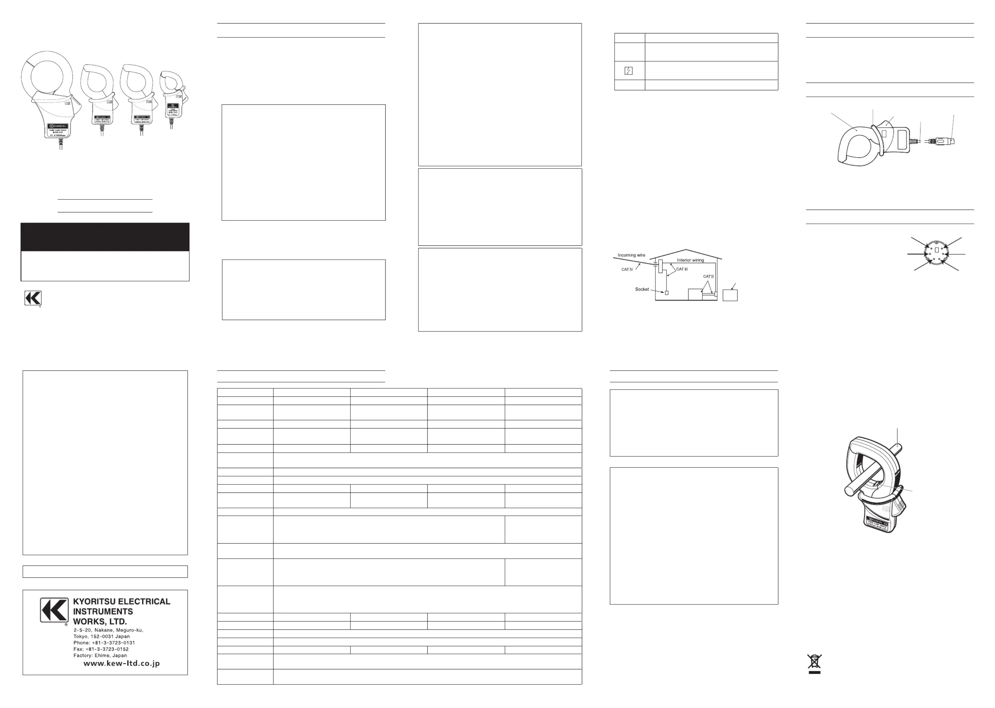
Kyoritsu 8126 Manual


Læs gratis den danske manual til Kyoritsu 8126 (1 sider) i kategorien Måling. Denne vejledning er vurderet som hjælpsom af 12 personer og har en gennemsnitlig bedømmelse på 3.9 stjerner ud af 6.5 anmeldelser. Har du et spørgsmål om Kyoritsu 8126, eller vil du spørge andre brugere om produktet?

Side 1/1
INSTRUCTIONMANUAL
POWERCLAMPSENSOR
POWER CLAMP SENSOR
Series
MODEL 8124/8125/8126/8127
MODEL
8127
MODEL
8126
MODEL
8125
MODEL
8124
TOKYO, JAPAN
1. Safety warnings
 ○
This instrument has been designed, manufactured and
tested according to IEC
61010
: Safety requirements for
ElectronicMeasuringapparatus,anddeliveredinthebest
condition after passing quality control tests. This
instruction manual containswarnings and safety rules
which have to be observed by the user to ensure safe
operationof the instrument andto maintain itin safe
condition. Therefore, read through these operating
instructionsbeforeusingtheinstrument.
#
WARNING
Read through and understand instructions contained
inthismanualbeforeusingtheinstrument.
Keep the manual at hand to enable quick reference
whenevernecessary.
The instrument is to be used only in its intended
applications.
Theoperating instructions described inthe manual
mustbeobserved.
Understand and follow all the safety instructions
containedinthemanual.Itisessentialthattheabove
instructions are adhered to. Failure to follow the
aboveinstructionsmaycauseinjuryandorinstrument
damage. Kyoritsu is by no means liable for any
damageresultingfromtheinstrument incontradiction
tothiscautionarynote.
The symbol
#
indicated on the instrument, means that
theusermustrefertotherelatedpartsinthemanualfor
safeoperationoftheinstrument.Itisessentialtoreadthe
instructions wherever the
#
symbol appears in the
manual.
#
DANGER 
is reserved for conditions and actions
thatarelikelytocauseseriousorfatal
injury.
#
WARNING
is reserved for conditions and actions
thatcancauseseriousorfatalInjury.
#
CAUTION 
is reserved for conditions and actions
t h a t c a n c a u s e m i n o r i n j u r y o r
instrumentdamage.
#
DANGER
Never make measurement on a circuit in which
the electrical potential exceeds AC
300
V using
MODEL
8127
and AC
600
V using MODEL
8124
,
8125
and
8126
.
Donot make measurement whenthunderrumbling.
If the instrument is in use, stop the measurement
immediately and remove the instrument from the
measuredobject.
Donotattempttomakemeasurementinthepresence
of flammable gasses. Otherwise, the use of the
instrumentmaycausesparking,whichcanleadtoan
explosion.
The transformer jaws are madeof metal and their
tips are not completely insulated. Be especially
careful about the possible shorting where the
measuredobjecthasexposedmetalparts.
Neverattempttousetheinstrumentifit
ssurfaceor
yourhandarewet.
Do not exceed the maximum allowable input of any
measuringrange.
#
WARNING
Never attempt to make any measurement, if any
abnormalconditions are noted, suchas broken case,
andexposedmetalparts.
Do n o t i n stall s ubsti t u t e p a rts o r m a k e an y
modification to the instrument. Return the instrument
to the distributor from who you purchased this
instrument for repair or re-calibration in case of
suspectedfaultyoperation.
Alwayskeepyourfingersandhandsbehindthebarrier
ontheinstrumenttoavoidthepossibleshockhazard.
#
CAUTION
Donotsteponorpinchthecordtopreventthejacket
ofcordfrombeingdamaged.
Theoutput connector shall beremoved orconnected
without clamping a conductor. Otherwise, it may
causeafailure.
Do notexpose the instrument to direct sunlight,high
temperatures,humidityordew.
Never give shocks, such as vibration or drop, which
maydamagetheinstrument.
Use a damp cloth and detergent for cleaning the
instrument.Donotuseabrasivesorsolvents.
Safety symbols
#
Refertotheinstructionsinthemanual.
Indicates a Instrument with double or reinforced
insulation
Indicatesthatthisinstrumentcanclamponbare
conductors.
IndicatesAC
MeasurementCategory

To ensure safe operation of measuring instruments, IEC
61010
establishessafety standards for various electrical
environ-ments, categorized as O to CAT IV, and called
measurement categories. Higher-numbered categories
correspond to electrical environments with greater
momentaryenergy,soameasuringinstrumentdesignedfor
CATIIIenvironmentscanenduregreatermomentaryenergy
thanonedesignedforCATII.
O :Circuits which arenot directly connected to the
mainspowersupply.
CATII :ElectricalcircuitsofequipmentconnectedtoanAC
electricaloutletbyapowercord.
CATIII:Primary electrical circuits of the equipment
connected directly to the distribution panel, and
feedersfromthedistributionpaneltooutlets.
CATIV:The circuit from the service drop to the service
entrance, and to the power meter and primary
overcurrentprotectiondevice(distributionpanel).
O: Device which is
not directly
connected to the
mains power supply
2. Features
ThisisaclampsensorforourPowermeter.
Designed to international safety standard
IEC
61010
-
2
-
032
CATIIIPollutionDegree
2
3. Instrument layout
TransformJaws
Barrier
Trigger
Cable
Outputconnector
Barrier:It is a part providing protection against
electricalshockandensuringtheminimum
requiredairandcreepagedistances.
4. Din plug pin assignment
5
3
1
2
4
6
3
:GNDpin
5
:Outputsignalpin
1
,
2
,
4
and
6
:Nouse
*Above figure shows the pin assignment seeing the
Clampsensorfromoutputconnectorpart. Thefigure
of the pin assignment of connection terminal is
symmetricaltoabovefigure.
6. Operating instructions
#
DANGER
Never make measurement on a circuit in which the
electricalpotential exceeds AC
300
Vusing MODEL
8127
andAC
600
VusingMODEL
8124
,
8125
and
8126
inorder
toavoidpossibleshockhazard.
The transformer jaws are made of metal and their tips
are not completely insulated. Be especially careful
aboutthepossibleshorting wherethemeasured object
hasexposedmetalparts.
#
CAUTION
Take sufficient care to avoid shock, vibration or
excessive force when handling the instrument.
Otherwise, precisely adjusted transformer jaws will be
damaged.
When transformer jaws do not fully close, never try to
close them byforce, but make them free to move and
try again. If a foreign substance is stuck in the jaw
tips,removeit.
When making current measurements, keep the
transformerjawsfullyclosed.
Otherwise, accurate measurements cannot be taken.
Maximumconductorsizeisasfollows.
MODEL
8124
:
68
mmindiameter
MODEL
8125
/
8126
:
40
mmindiameter
MODEL
8127
:
24
mmindiameter
Hold the inserting part (except for the cable) and
disconnect the Outputconnector from the measuring
instrumentsoasnottocauseabreakinthecord.
6
-
1
Measurementprocedures
(
1
)Connect the Output connector to the Input terminal of
themeasuringinstrument.
(
2
)Press the Trigger to open the transformer jaws and
clampontooneconductor.
Inthiscase,themeasuredconductorshallbeatthecenter
ofthejaws.
When connecting asensorwith a Power meter (our
Power meter, MODEL
6300
, etc.) match the arrow
mark(Powersourcetoload), whichis indicatedonthe
transformer jaws, with the current flowing direction in
order tosynchronize the phases of measured current
andoutputvoltage.
(
3
)Ensure that the tips of transformer jaws are firmly
closed.
Conductor
Load
Current direction
arrow
Power
source
6
-
2
SettingforPowermeter

When using any of these sensors with KEW
6305
or
6315
,please refer to the instruction manual, eitherof
which you're using, and carefully check sensor type
settingsandavailablecurrentranges.
This instrument sat isfies the marking
requirement defined in the WEEE Directive
(
2002
/
96
/EC). This symbol indicates separate
collection for electrical and electronic
equipment.
92
-
1640
E
5
-
22
DISTRIBUTOR
Kyoritsu reserves the rights to change specifications or designs
describedinthismanualwithoutnoticeandwithoutobligations.
Model
8124 8125 8126 8127
Ratedvoltage AC
1000
Arms(
1414
Apeak) AC
500
Arms(
707
Apeak) AC
200
Arms(
283
Apeak) AC
100
Arms(
141
Apeak)
Outputvoltage AC
0
500
mV
(AC
500
mV/AC
1000
A):
0
.
5
mV/A
AC
0
500
mV
(AC
500
mV/AC
500
A):
1
mV/A
AC
0
500
mV
(AC
500
mV/AC
200
A):
2
.
5
mV/A
AC
0
500
mV
(AC
500
mV/AC
100
A):
5
mV/A
Measuringrange AC
0
1000
A AC
0
500
A AC
0
200
A AC
0
100
A
Accuracy
(Input:sinewave)
±
0
.
5
%rdg
±
0
.
2
mV(
50
/
60
Hz)
±
1
.
5
%rdg
±
0
.
4
mV(
40
1
kHz)
±
0
.
5
%rdg
±
0
.
1
mV(
50
/
60
Hz)
±
1
.
0
%rdg
±
0
.
2
mV(
40
1
kHz)
±
0
.
5
%rdg
±
0
.
1
mV(
50
/
60
Hz)
±
1
.
0
%rdg
±
0
.
2
mV(
40
1
kHz)
±
0
.
5
%rdg
±
0
.
1
mV(
50
/
60
Hz)
±
1
.
0
%rdg
±
0
.
2
mV(
40
1
kHz)
Phasecharacteristics
±
1
degwithin(at
10
1000
A/
45
65
Hz)
±
1
degwithin(at
5
500
A/
45
65
Hz)
±
1
degwithin(at
2
200
A/
45
65
Hz)
±
2
degwithin(at
1
100
A/
45
65
Hz)
Temperature&humidityrange
(Guaranteedaccuracy)
23
±
5
,relativehumidity:
85
%orless(nocondensation)
Operatingtemperaturerange
0
50
,relativehumidity:
85
%orless(nocondensation)
Storagetemperaturerange
-
20
60
,relativehumidity:
85
%orless(nocondensation)
Maximumpermissibleinput
AC
1000
Armscontinuous(
50
/
60
Hz)
AC
500
Armscontinuous(
50
/
60
Hz) AC
200
Armscontinuous(
50
/
60
Hz) AC
100
Armscontinuous(
50
/
60
Hz)
Output
impedance
Approx.
1
Ω
Approx.
2
Ω
Approx.
5
Ω
Approx.
11
Ω
Locationforuse Altitudeupto
2000
m,Indoors
Applicable
standards
IEC
61010
-
1
,IEC
61010
-
2
-
032
MeasurementCAT
(
600
Vrms)
Pollutiondegree
2
IEC
61326
-
1
(EMC)
IEC
61010
-
1
,IEC
61010
-
2
-
032
MeasurementCAT
(
300
Vrms)
Pollutiondegree
2
IEC
61326
-
1
(EMC)
Environmental
standards
EURoHSDirectivecompliant
Withstand
voltage
AC
5160
Vrms(
50
/
60
Hz)for
5
sec.
  
betweenJawandenclosure
  
betweenenclosureandoutputterminal
  
betweenJawandoutputterminal
AC
3470
Vrms(
50
/
60
Hz)for
5
sec.
  
betweenJawandenclosure
  
betweenenclosureandoutputterminal
  
betweenJawandoutputterminal
Insulation
resistance
50
M
Ω
orgreaterat
1000
V
  
betweenJawandenclosure
  
betweenenclosureandoutputterminal
  
betweenJawandoutputterminal
ConductorSize
Approx.
68
mmindiameter(max.) Approx.
40
mmindiameter(max.) Approx.
40
mmindiameter(max.) Approx.
24
mmindiameter(max.)
Dimension
186
(L)
×
129
(W)
×
53
(D)
mm
128
(L)
×
81
(W)
×
36
(D)
mm
128
(L)
×
81
(W)
×
36
(D)
mm
100
(L)
×
60
(W)
×
26
(D)
mm
Cablelength Approx.
3
m
Outputterminal MINIDIN
6
PIN
Weight Approx.
510
g Approx.
260
g Approx.
260
g Approx.
160
g
Accessories Instructionmanual
Cablemarker
Option MODEL
7146
Banans
Φ
4
adjusterplug
MODEL
7147
Extensioncable
5. Specifications


Produkt Specifikationer

Mærke: Kyoritsu
Kategori: Måling
Model: 8126

Har du brug for hjælp?

Hvis du har brug for hjælp til Kyoritsu 8126 stil et spørgsmål nedenfor, og andre brugere vil svare dig