IorLeakageCurrentClampSensor
○ KEW 8177/ 8178 Ior leakage clamp sensor (Sensor) has been
designed, manufactured and tested according to IEC 61010: Safety
requirements for Electronic Measuring apparatus, and delivered in
the best condition after passing quality control tests. This instruction
manual contains warnings and safety rules which have to be
observed by the user to ensure safe operation of the Sensor and to
maintain it in safe condition. Therefore, read through these
operating instructions before using the Sensor.
● Read through and understand instructions contained in this
manual before starting to use the Sensor.
● Keep the manual at hand to enable quick reference whenever
● The Sensor is to be used only in its intended applications.
● Understand and follow all the safety instructions contained in the
It is essential that the above instructions are adhered to. Failure to
follow the above instructions may cause injury and or damage the
The symbol marked on the Sensor, means that the user must refer
to the related parts in the manual for safe operation of the Sensor. It is
essential to read the instructions wherever symbol appears in the
DANGER : is reserved for conditions and actions that are likely
to cause serious or fatal injury.
WARNING : reserved for conditions and actions that can cause
CAUTION : is reserved for conditions and actions that can
cause minor injury or damage the Sensor.
● Do not attempt to make measurement in the presence of
flammable gasses. Otherwise, the use of the Sensor may cause
sparking, which can lead to an explosion.
● Wear insulated protective gears to reduce the risks such as
electrical shock at the workplace.
● Never make measurement in CAT III environment if electrical
potentials of 300 V AC or higher exist in the circuit to be tested.
● Do not exceed the maximum allowable input of any measuring
● The Sensor is to be used only in its intended applications or
Otherwise, safety functions equipped with the Sensor will not
work, and Sensor damage or serious personal injury may occur.
Verify proper operation on a known source before starting to use
● Do not make measurement when thunder rumbling. If the Sensor
is in use, stop the measurement immediately and remove the
Sensor from the measured object.
● The transformer jaws are designed so as not to short-circuiting
the object under test; however, be especially careful about the
possible shorting where the measured object has uninsulated
● Never attempt to use the Sensor if it's surface or your hand is wet.
● Always keep your fingers and hands behind the barrier on the
Sensor to avoid the possible shock hazard.
● Never attempt to make any measurement, if any abnormal
conditions are noted, such as broken case, and exposed metal
● Do not install substitute parts or make any modification to the
Return the Sensor to your local distributor for repair or
re-calibration in case of suspected faulty operation.
● The Sensor is not dust nor water-proof. Don't use the Sensor at
dusty places or to be spattered.
● Take sufficient care to avoid shock when handling the Sensor and
also to prevent foreign substance from being stuck between the
● Do not step on or pinch the cable to prevent the jacket of cable
● Do not bend or pull the cable of the clamp sensor.
● Connect/ disconnect the output terminal without clamping onto a
● Do not expose the Sensor to direct sunlight, high temperature,
● Never give shocks, such as vibration or drop, which may damage
● Use a damp cloth and detergent for cleaning the Sensor. Do not
use abrasives or solvents.
User must refer to the explanations in the instruction manual.
Instrument with double or reinforced insulation
Indicates that this instrument can clamp on live bare conductors when
the voltage to be tested is below Circuit – Ground-to-Earth voltage
against the indicated Measurement Category.
Crossed-out wheel bin symbol (according to WEEE Directive:
2002/96/EC) indicating that this electrical product may not be
treated as household waste, but that it must be collected and
To ensure safe operation of measuring instruments, IEC 61010
establishes safety standards for various electrical environments,
categorized as O to CAT IV, and called measurement categories.
Higher-numbered categories correspond to electrical environments
with greater momentary energy, so a measuring instrument designed
for CAT III environments can endure greater momentary energy than
: Circuits which are not directly connected to the mains
CAT II : Electrical circuits of equipment connected to an AC
electrical outlet by a power cord.
CAT III : Primary electrical circuits of the equipment connected
directly to the distribution panel, and feeders from the
distribution panel to outlets.
CAT IV : The circuit from the service drop to the service entrance,
and to the power meter and primary overcurrent
protection device (distribution panel).
● KEW 8177/ 8178 are clamp sensors to measure Ior leakage
● Provides the best phase characteristics when combined and used
with our KEW 5050 Ior leakage logger.
● Designed to meet IEC 61010-2-032 (CAT III, Pollution degree 2)
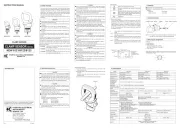
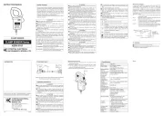
Barrier: provides protection against electrical shock and ensuring the
required minimum air and creepage distances. Always keep
your fingers behind the barrier during a measurement.
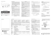
4. DIN plug pin assignment
● Above figure shows the pin assignment seeing the clamp sensor
from output connector part. The figure of the pin assignment of
connection terminal is symmetrical to above figure.
Power to the Sensor is supplied from KEW 5050 via cable. Connect
a power supply of +5 V across GND pin (no.3) and Power pin (no. 1).
● The internal memory stores the information about sensor type,
serial no. and phase correction value. The Sensor is automatically
detected by KEW 5050* by its communication function.
* KEW 5050 is an Ior leakage logger which has a reference voltage
input terminal and four current input terminals and can measure
and record resistive leakage current (Ior) up to four systems.
For its specs and functions, please see the instruction manual for
5. Operating instructions
The rated ground-to-voltage is CAT III 300 V. Never make
measurement if the potential of the circuit under test exceeds 300 V.
● The transformer jaws are designed so as not to short-circuiting
the object under test; however, be especially careful about the
possible shorting where the measured object has uninsulated
● Take sufficient care to avoid shock, vibration or excessive force
when handling the Sensor. Otherwise, precisely adjusted
transformer jaws will be damaged.
● When transformer jaws do not fully close, never try to close them
by force, but make them free to move and try again. If a foreign
substance is stuck in the jaw tips, remove it.
● Hold the inserting part (except for the cable) and disconnect the
output terminal from the measuring instrument so as not to cause
● Do not forcibly open the jaws if they are frozen.
● The Sensor is dedicated to our KEW 5050 Ior Leakage
Logger. When connecting to our other models, such as KEW
5010/ 5020, the sensor auto-detecting function doesn't work.
● Ensure that the transformer jaws are fully closed while clamping
onto a conductor to be tested; otherwise, accurate measurements
cannot be taken. See 6. Specification in this manual for maximum
● Sensitive transformer jaws are used for leakage clamp sensor.
Because of the characteristics of split-core type transformer, it is
impossible to eliminate the interference of external magnetic field
completely. If there is a presence of strong magnetic field, use the
Sensor at a distance as far as possible from it. The followings are
the typical things which generate magnetic field.
・Conductor fed large current
・Equipment which has magnet
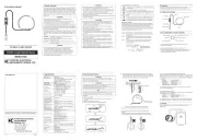
(1) Attach the color markers, supplied with KEW 5050, to clamp
sensors for easy recognition. Colors of the marker are harmonized
with that of current input terminals (red: A1, yellow: A2, blue: A3,
(2) Connect the output terminal to the current input terminal on KEW
(3) Power on KEW 5050 and wait for a while until the connected
sensor is identified. * Sensor detection can be performed on
Basic setting screen. See 6.2 Basic settings in the manual
for KEW 5050 for details.
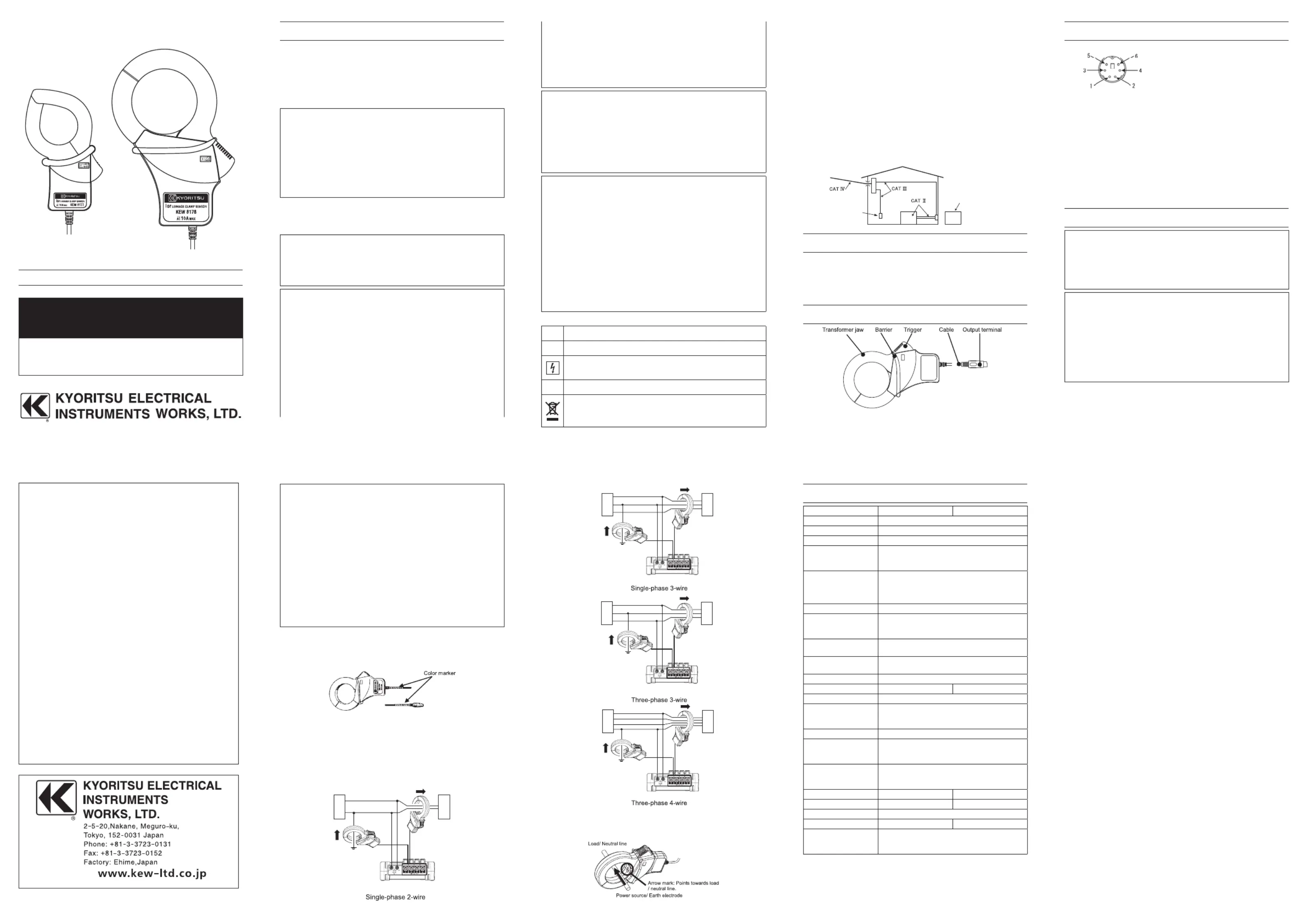
(4) Connect the clamp sensor and the voltage test lead properly.
(5) Ensure that the arrow mark on the clamp sensor points towards
load side (towards neutral at earth line measurement). Ensure that
the tips of transformer jaws are firmly closed.
Model name KEW 8177 KEW 8178
Rated current 10 A (rms) AC (14.1 A peak)
Output voltage 500 mV AC/ 10 A AC (50 mV/ A)
Measuring range 0 – 10 A AC
± ±1.0%rdg 0.025 mV (40 - 70 Hz)
± ±4.0%rdg 0.025 mV (30 - 5 kHz, with inputs
(45 – 70 Hz while combining with KEW 5050,
under the input of 10% or more of KEW 5050
Current consumption 8.6 mA max.
23 5°C, relative humidity 85% or less ±
-10 to 50°C, relative humidity 85% or less
-20 to 60°C, relative humidity 85% or less
Max. allowable input*1 100 A (rms) AC, continuous, (40 - 70 Hz)
Output impedance Approx. 100 or less Approx. 60 or lessΩ Ω
Location for use Altitude up to 2000 m, in-door use
IEC61010-1, IEC61010-2-032
CAT III 300 V Pollution degree 2
Environmental standard EU RoHS directive compliant
3470 V AC (rms, 50/ 60 Hz) / 5 sec.
Any combination of: engaged Jaws, enclosure,
Any combination of: engaged Jaws, enclosure,
Conductor size Approx. Ø40 mm max. Approx. Ø68 mm max.
128(L) 81(W) 36(D)mm 186(L) 129(W) 53(D)mm× × × ×
Weight Approx. 280 g Approx. 560 g
(KEW 8177: M-9095, KEW 8178: M-9094*2)
*1: Allowable limit values in the case of in correct operations. Accuracy
is not guaranteed for current inputs higher than the rated current.
*2: Carrying case isn't packed with the clamp sensor supplied as