Manfrotto MVM500A Manual
Manfrotto
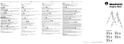
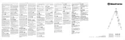
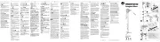
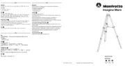
Kamerastativ
MVM500A

| Mærke: | Manfrotto |
| Kategori: | Kamerastativ |
| Model: | MVM500A |
| Vægt: | 2100 g |
| Produktfarve: | Sort |
| Materiale: | Aluminium |
| Montering: | 1/4", 3/8" |
| Højde (min.): | 77 mm |
| Højde (maks.): | 200.5 mm |
| Maksimal vægtkapacitet: | 5 kg |
Har du brug for hjælp?
Hvis du har brug for hjælp til Manfrotto MVM500A stil et spørgsmål nedenfor, og andre brugere vil svare dig
Kamerastativ Manfrotto Manualer

9 November 2025

30 Oktober 2025
21 August 2025
21 August 2025
29 Juli 2025
15 Juli 2025
14 Juli 2025
14 Juli 2025
9 Juli 2025
8 Juli 2025
Kamerastativ Manualer
- Essentiel B
- Flycam
- Laserliner
- Sachtler
- Cambo
- Insta360
- GoPro
- Gravity
- Rollei
- Hama
- Godox
- IOptron
- Rolls
- Really Right Stuff
- ENDORFY
Nyeste Kamerastativ Manualer

20 December 2025

8 December 2025

6 December 2025

5 December 2025

1 December 2025

1 December 2025

29 November 2025

29 November 2025

28 November 2025

28 November 2025