Manfrotto Salon 230 Manual
| Mærke: | Manfrotto |
| Kategori: | Stativ |
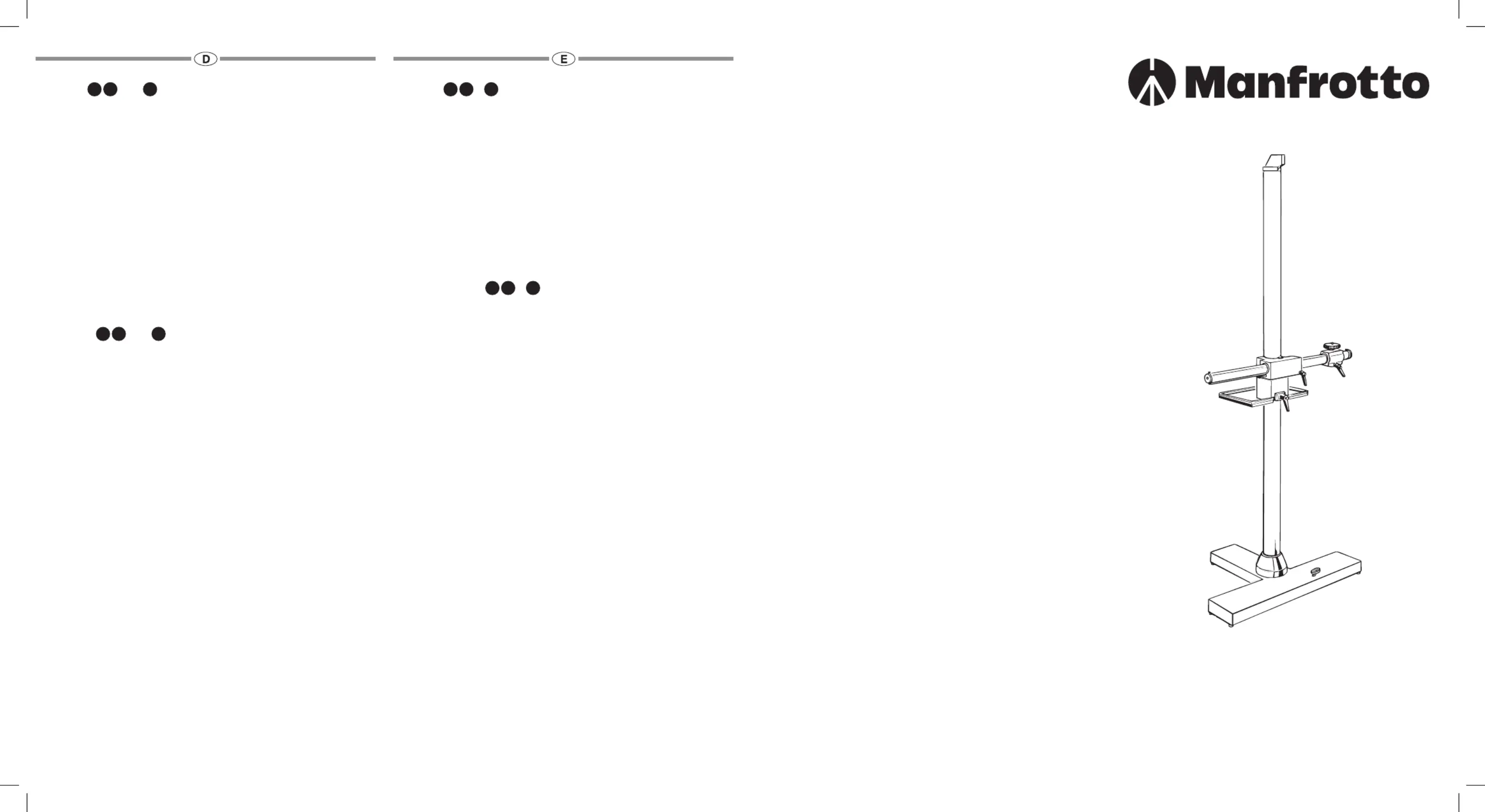
| Model: | Salon 230 |
Har du brug for hjælp?
Hvis du har brug for hjælp til Manfrotto Salon 230 stil et spørgsmål nedenfor, og andre brugere vil svare dig
Stativ Manfrotto Manualer
30 Marts 2025
28 Marts 2025

28 Marts 2025
28 Marts 2025
28 Marts 2025
28 Marts 2025
27 Marts 2025
11 Februar 2025
11 Februar 2025
10 Februar 2025
Stativ Manualer
- GVM
- Vinten
- ProMediaGear
- Kaiser Fototechnik
- REVO
- Auray
- Gitzo
- Bresser
- Trust
- FeiYu-Tech
- FeiyuTech
- 3 Legged Thing
- Kogan
- Nikon
- Rode
Nyeste Stativ Manualer
3 April 2025
2 April 2025
2 April 2025
2 April 2025
2 April 2025
2 April 2025
2 April 2025
2 April 2025
2 April 2025

2 April 2025