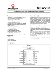
Microchip HV257 Manual


Læs gratis den danske manual til Microchip HV257 (26 sider) i kategorien Ikke kategoriseret. Denne vejledning er vurderet som hjælpsom af 7 personer og har en gennemsnitlig bedømmelse på 4.9 stjerner ud af 4 anmeldelser. Har du et spørgsmål om Microchip HV257, eller vil du spørge andre brugere om produktet?

Side 1/26
2017 Microchip Technology Inc. DS20005827A-page 1
HV257
Features
Thirty-two Independent High-voltage Amplifiers
300V Operating Voltage
295V Output Voltage
2.2V/µs Typical Output Slew Rate
Adjustable Output Current Source Limit
Adjustable Output Current Sink Limit
Internal Closed-loop Gain of 72V/V
12 M Feedback Impedance
Layout Ideal for Die Applications
Applications
Microelectromechanical Systems (MEMS) Driver
Piezoelectric Transducer Driver
Optical Crosspoint Switches
(Using MEMS Technology)
General Description
The HV257 is a 32-channel, high-voltage
sample-and-hold amplifier array integrated circuit. It
operates on a single high-voltage supply, up to 300V,
and two low-voltage supplies, VDD and VNN.
All 32 sample-and-hold circuits share a common
analog input, VSIG
. The individual sample-and-hold
circuits are selected by a five-to-32 logic decoder. The
sampled voltage on the holding capacitor is buffered by
a low-voltage amplifier and is magnified by a
high-voltage amplifier with a closed-loop gain of 72V/V.
The internal closed-loop gain is set for an input voltage
range of 0V to 4.096V. The input voltage can be up to
5V, but the output will saturate. The maximum output
voltage swing is 5V below the VPP high-voltage supply.
The outputs can drive capacitive loads of up to
3000 pF.
The maximum output source and sink current can be
adjusted by using two external resistors. An external
RSOURCE resistor controls the maximum sourcing
current, and an external RSINK resistor controls the
maximum sinking current. The current limit is
approximately 12.5V divided by the external resistor
value. The setting is common for all 32 outputs. A
low-voltage silicon junction diode is made available to
help monitor the die temperature.
Package Type
100-lead MQFP
(Top view)
1
100
See Table 3-1 for pin information.
32-Channel High-Voltage Sample-and-Hold Amplifier Array
R
HVOUT0
AVNN
AVDD
S/H-0
5 to 32
Decoder
VSIG
A0
A1
A2
A3
EN
A4
R
S/H-1
HVOUT1
R
S/H-31
HVOUT31
VPP
AVDD
AVNN
AVNN
CH
-
+
-
+
Q0
Q1
Q31
HVOUT
Current
Sink
Limiting
To all HVOUT
amplifiers
RSOURCE
RSINK
DVDD
AVNN
DGND
AGND
VPP
AVDD
To internal VPP bus
To internal analog VDD bus
To internal analog VNN bus
To internal digital VDD bus
To internal digital VNN bus
DVDD
DVNN
AVDD
AVNN
CH
CH
BYP-VPP BYP-AVDD BYP-AVNN Anode Cathode
Bias Circuit
-
+
-
+
-
+
-
+
HVOUT
Current
Source
Limiting
To all HVOUT
amplifiers 71R
VPP
AVNN
71R
VPP
AVNN
71R
HV257
DS20005827A-page 2 2017 Microchip Technology Inc.
Functional Block Diagram


Produkt Specifikationer

Mærke: Microchip
Kategori: Ikke kategoriseret
Model: HV257

Har du brug for hjælp?

Hvis du har brug for hjælp til Microchip HV257 stil et spørgsmål nedenfor, og andre brugere vil svare dig


Ikke kategoriseret Microchip Manualer
Ikke kategoriseret Manualer

Nyeste Ikke kategoriseret Manualer
Elektrobock

Elektrobock PT44 Manual

14 September 2025
BSS Audio

BSS Audio FDS-366T Manual

14 September 2025
Systemair

Systemair Airline R-114 Manual

14 September 2025
IFM

IFM SU2031 Manual

14 September 2025
IMC Networks

IMC Networks 232CL9R Manual

14 September 2025
Melissa & Doug

Melissa & Doug 9336 Manual

14 September 2025
Opus

Opus dataPREDATOR Manual

13 September 2025