© 2001 Microchip Technology Inc. DS21348A
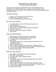
Charge Pump DC-TO-DC Voltage Converter
FEATURES
■Converts +5V Logic Supply to ±5V System
■Wide Input Voltage Range .................... 1.5V to 12V
■Ecient Voltage Conversion ......................... 99.9%
■Excellent Power Eciency ............................... 98%
■Low Power Consumption ............ 80µA @ V IN = 5V
■Low Cost and Easy to Use
— Only Two External Capacitors Required
■RS-232 Negative Power Supply
■Available in 8-Pin Small Outline (SOIC) and 8-Pin
Plastic DIP Packages
■Improved ESD Protection ..................... Up to 10kV
■No External Diode Required for High Voltage
Operation
■Frequency Boost Raises F OSC to 45kHz
GENERAL DESCRIPTION
The TC1044S is a pin-compatible upgrade to the Indus-
try standard TC7660 charge pump voltage converter. It
converts a +1.5V to +12V input to a corresponding –1.5V
to –12V output using only two low cost capacitors, eliminat-
ing inductors and their associated cost, size and EMI.
Added features include an extended supply range to 12V,
and a frequency boost pin for higher operating frequency,
allowing the use of smaller external capacitors.
The on-board oscillator operates at a nominal frequency
of 10kHz. Frequency is increased to 45kHz when pin 1 is
connected to V+. Operation below 10kHz (for lower supply
current applications) is possible by connecting an external
capacitor from OSC to ground (with pin 1 open).
The TC1044S is available in both 8-pin DIP and
8-pin small outline (SOIC) packages in commercial and
extended temperature ranges.
FUNCTIONAL BLOCK DIAGRAM
TC1044S
GND
INTERNAL
VOLTAGE
REGULATOR
RC
OSCILLATOR
VOLTAGE–
LEVEL
TRANSLATOR
2
V+CAP +
8 2
7
6
OSC
LV
3
LOGIC
NETWORK
VOUT
5
CAP –
4
1
BOOST
ORDERING INFORMATION
Part No. Package Temp. Range
TC1044SCOA 8-Pin SOIC 0° °C to +70 C
TC1044SCPA 8-Pin Plastic DIP 0° °C to +70 C
TC1044SEOA 8-Pin SOIC – 40° °C to +85 C
TC1044SEPA 8-Pin Plastic DIP – 40° °C to +85 C
TC1044SIJA 8-Pin CerDIP – 25° °C to +85 C
TC1044SMJA 8-Pin CerDIP – 55° °C to +125 C
TC7660EV Charge Pump Family Evaluation Kit
PIN CONFIGURATION (DIP AND SOIC)
1
2
3
4
8
7
6
5
TC1044SCPA
TC1044SEPA
TC1044SIJA
TC1044SMJA
BOOST
CAP+
GND
CAP–VOUT
LOW
VOLTAGE (LV)
OSC
+
V1
2
3
4
8
7
6
5
TC1044SCOA
TC1044SEOA
BOOST
CAP +
GND
CAP –VOUT
LOW
VOLTAGE (LV)
OSC
+
V