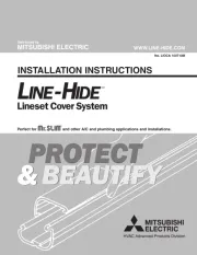
Mitsubishi Line-Hide CD-140 Manual
Mitsubishi
Ikke kategoriseret
Line-Hide CD-140
Læs nedenfor 📖 manual på dansk for Mitsubishi Line-Hide CD-140 (4 sider) i kategorien Ikke kategoriseret. Denne guide var nyttig for 2 personer og blev bedømt med 4.4 stjerner i gennemsnit af 1.5 brugere
Side 1/4

INSTALLATION INSTRUCTIONS
& BEAUTIFY
PROTECT
&BEAUTIFY
PROTECT
No. LIOCA 100710M
WWW.LINE-HIDE.COM
Distributed by
MITSUBISHI ELECTRIC
Perfect for and other A/C and plumbing applications and installations.

Installing Line-Hide
Your Line-Hide installation will go smoothly if you follow — in
order
— the steps outlined in these instructions: determine lay-
out; install entry fittings and joint bases; install Line
Tube base;
insert Lineset: assemble tube, and assemble joints. When
you’ve finished, caulk the lineset entry and exit points on the
wall to ensure the protection of the Lineset and of the building.
Step 1: Layout
Identify the inlet and out-
let points for the Lineset
you’ll be installing within the Line-Hide
product, and determine the simplest
and most appropriate route for the
installation to follow. In most cases you’ll want your installation
to run perfectly vertical and nearly horizontal (a slight grade will
enable condensate lines to drain) and adhere to 90 degree
turns. Sketching your installation on a contractor worksheet or
graph paper will help you to determine how much tubing and
how many elbows, joints, and other pieces you will need.
Step 2: Install Entry Fittings and Joint Bases
Most Line-Hide entry fittings and joints (including elbows)
include a base and a cover. Once you’ve determined where
your joints will be, install the bases. If you’re installing on wood,
simply position the base, and fasten it to the wall, using wood
screws. Don’t overtighten, or you’ll risk cracking the plastic.
For installations on a brick wall, mark the location for
each screw, and drill an anchor hole
using a masonry bit; then use
appropriate anchors and
screws.
Step 3:
Install Line
Tube Base
Measure the distance between the molded stops of each joint
base, and determine the length of tube needed. Line-Hide Line
T
ube is manufactured in six-and-one-half-foot (two-meter)
lengths so some straight runs are fabricated using two or more
lengths of tube and a socket/coupling.
T
o
cut tube, measure and mark
the appropriate length;
then draw a perpendicu
-
lar guideline across the
tube. Use a hacksaw to cut
the tube along the line, and
then use a file to smooth the
cut edge.
INSTALLATION INSTRUCTIONS
WARNING! Before you begin . . .
Whenever you’re working with tools, it’s a good idea
to wear appropriate safety gear: helmet, protective goggles, and gloves. If
you’re working high above the ground, be sure that you have sound footing.
To attach the Line Tube
base to the wall, first use
the tip of a screwdriver to
make a hole in the central
rib of the base (thin spots
are moulded in to accommodate installation). Then put a screw
through the hole in the tube, and tighten it to the wall. Be care-
ful not to overtighten, for you may distort the tube. For the
smaller sizes (the 60 and 75 series), place screws approximate-
ly every twelve inches. For the larger sizes (the 100 and 140
series), use screws approximately every six inches.
Step 4: Install the Lineset
Unwind insulated refrigerant lines, and place into straight portion
of the tube. When installing insulated refrigerant pipe into a cor-
ner, adjust the pipe to the shape of the joint, and gently bend the
insulated refrigerant pipe without forcing it. Bending too quickly
can cause kinks in insulated refrigerant pipe and can pinch drain
pipe. Also try to avoid compressing the pipe insulation.
A Saddle Band (NV-S short or
NV-L long) can be used to fas-
ten the insulated refrigerant
pipe, drain pipe, and electric
cable together in the Line
Tube. The saddle snaps to the
central rib of the tube base.
Thread the band through the
saddle and around the piping and cable, and pull it tight. This pro-
cedure will help to keep the pipes and wiring in place.
As a general rule, use one saddle band for every three feet (one
meter) of tube.
Step 5: Assemble
the Line
T
ube
When the Lineset is in
position, attach the tube
cover to the base. Slip
the lip on the short
edge of the cover into the trough on the high edge of the base.
Then squeeze the short end of the base while pushing the long
edge of the cover inward so that the lip and the trough engage.
Step 6: Assemble the Joints
With the Line Tube completely assembled, return to each joint,
and complete assembly
. Position the cover of each joint over its
base; line up the holes; then secure cover to bases with the
stainless steel screws provided.
Try to adhere to a grid defined
by parallel and perpendicular
lines and 90-degree angles
LIOCA 10/07 10M ©2007 Mitsubishi Electric and Electronics USA, Inc., HVAC
Produkt Specifikationer
Mærke: | Mitsubishi |
Kategori: | Ikke kategoriseret |
Model: | Line-Hide CD-140 |
Har du brug for hjælp?
Hvis du har brug for hjælp til Mitsubishi Line-Hide CD-140 stil et spørgsmål nedenfor, og andre brugere vil svare dig
Ikke kategoriseret Mitsubishi Manualer

7 Juni 2025

7 Juni 2025

7 Juni 2025

6 Juni 2025

5 September 2024

5 September 2024

5 September 2024

3 September 2024

3 September 2024

31 August 2024
Ikke kategoriseret Manualer
- Ikke kategoriseret Morphor
- Ikke kategoriseret Medisana
- Ikke kategoriseret Klauke
- Ikke kategoriseret Uniross
- Ikke kategoriseret Micsig
- Ikke kategoriseret Lawn Star
- Ikke kategoriseret Springfree
- Ikke kategoriseret Stamos
- Ikke kategoriseret Lervia
- Ikke kategoriseret Teltonika
- Ikke kategoriseret Stinger
- Ikke kategoriseret Clean Air Optima
- Ikke kategoriseret Eldat
- Ikke kategoriseret Audibax
- Ikke kategoriseret Banana Pi
Nyeste Ikke kategoriseret Manualer

7 Juni 2025

7 Juni 2025

7 Juni 2025

7 Juni 2025

7 Juni 2025

7 Juni 2025

7 Juni 2025

7 Juni 2025

7 Juni 2025

7 Juni 2025