PHOENIX CONTACT GmbH & Co. KG
Flachsmarktstraße 8, 32825 Blomberg, Germany
Fax +49-(0)5235-341200, Phone +49-(0)5235-300
中文 FRANÇAIS ENGLISH DEUTSCH
Einbauanweisung für den Elektroinstallateur
Installation notes for electrical personnel
Instructions d’installation pour l’électricien
Instrucciones de montaje para el instalador eléctrico
Istruzioni di installazione per l’elettricista
Instruções de instalação para o eletricista
Elektrik tesisatçı ıs için montaj talimatı
Инструкция по монтажу для электромонтажника
Dok.-Nr.: 83133830 - 00© PHOENIX CONTACT 2012 105274 - 00
RIFLINE complete RIF-2-...
•Installation, operation, and maintenance may only be carried out by qualified electri-
cians. Follow the installation instructions as described. When installing and operating
the device, the applicable regulations and safety directives (including national safety
directives), as well as general technical regulations, must be observed. The technical
data is provided in this package slip and on the certificates (conformity assessment,
additional approvals where applicable).
•Install the device in the control cabinet.
Take protective measures against electrostatic discharge!
•If there is a large load and inductive load, implement a contact protection circuit (e.g.
freewheeling diode, varistor, RC element) on the load. This prevents the coupling
of interference voltages to other system parts. The relays also achieve a longer
More detailed information can be found in the relay area of the Phoenix Con-
1.2. Note on designation and Order No.
The assembled RIF-2-R... modules consist of the relay base RIF-2-B... without
components and the plug-in relay (see Fig.1). For this reason, the designation and
Order No. of the assembled module printed on the packaging is not identical to that
on the RIF-2-B... relay base.
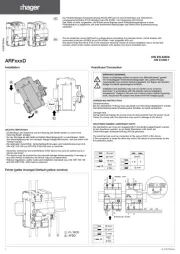
2.1. Function elements (Figs. 1/2)
Plug the optional double marker carrier (7) into the square recesses on the
base (C). Do not insert it into the terminal inspection holes (8/D).
2.2. Connection technology
UL requirement: Use copper cables that are - at minimum - approved for use above 75°C.
RIF-2-...-modules with push-in connection (Fig.3):
Rigid or flexible wire with ferrule diameter ≥ 0.34 mm² is plugged directly in the
clamping space (A). You can secure flexible conductors without ferrule reliably by
opening the spring beforehand with the pushbutton (B). Press the pushbutton (B)
also to release the conductor.
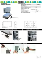
2.3. Fixing to the DIN rail
Place an end bracket at beginning and the end of eachRIF-2-... module strip. If sub-
ject to vibration, the DIN rail needs to be fixed at intervals of 10 cm
The end bracket can be used also for the following purposes:
•For voltages greater than 250 V between identical terminal points of adjacent mod-
•For safe isolation between neighboring modules
•For visual separation of functional groups.
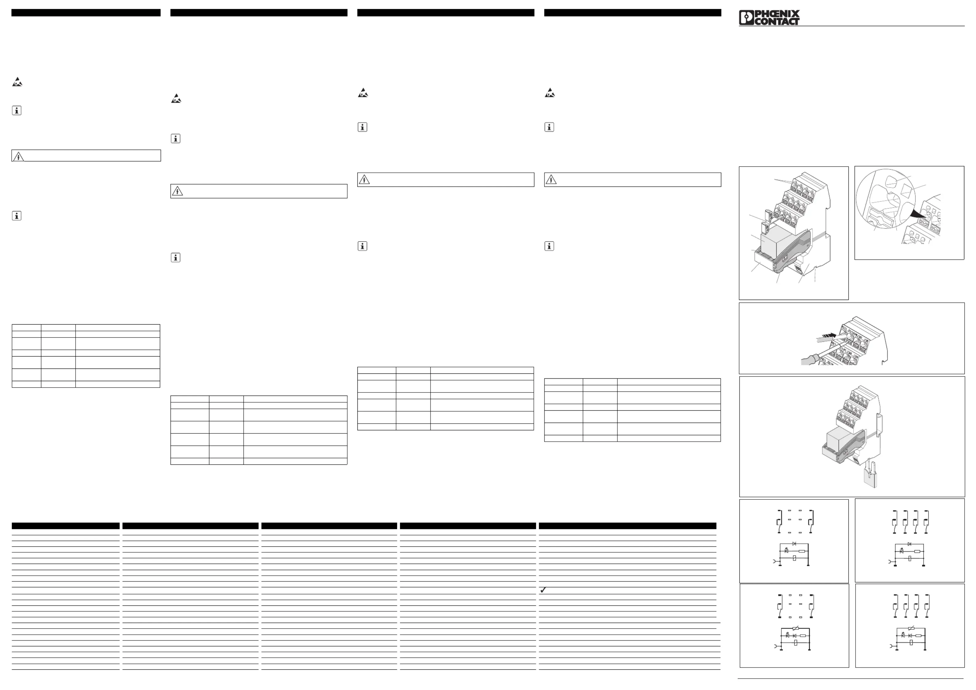
2.4. Bridging of voltage potentials (Fig. 4)
Identical voltage potentials of adjacent modules can be bridged with plug-in bridges
FBD... (A2 with FBD 2-6). The bridges have to snap in completely.
2x PDT contact with DC input (Fig. 5)
4x PDT contact with DC input (Fig. 6)
2x PDT contact with DC input (Fig. 7)
4x PDT contact with DC input (Fig. 8)
CAUTION: Never carry out work on the device when mains voltage is
Designation Order No. Description
STP 5-2 0800967 Double marker carrier
ZB 5 E.g., 1050004 Equipment marking label e.g. zack marker strip,
FBD 2-6 E.g., 3030336 Plug-in bridge, 2-pos.
E/UK 1201442 End bracket, for mounting on DIN rail NS 32 or
E/UK 1 1201413 End brackets, for supporting the ends of double-
level and three-level terminal blocks
CLIPFIX 35 3022218 Quick-mounting end clamp
1Bridge shaft for FBD 2-6
3Display / Interference suppression
module (depending on type)
4Optional equipment marking label
5Engagement lever for securing and
7Optional double marker carrier
8/D Inspection hole for terminal
APushbutton / B Terminal space
21
24
22
42
44
41 1
1
4
2
32
34
31
N
N
C
C
O
OM
COIL
A
1
1
1
1
Abb./Fig./Şekil/Рис./ 图 1
Abb./Fig./Şekil/Рис./ 图 3
2
1
2
4
22
42
44
41 1
1
4
2
32
34
31
N
N
C
C
O
OM
C
OI
L
A1
1
1
1
Abb./Fig./Şekil/Рис./ 图 4
Abb./Fig./Şekil/Рис./ 图 5
Abb./Fig./Şekil/Рис./ 图 7
Abb./Fig./Şekil/Рис./ 图 8
Abb./Fig./Şekil/Рис./ 图 6
Abb./Fig./Şekil/Рис./ 图 2
RIFLINE complete RIF-2-...
1. Sicherheitsbestimmungen
•Die Installation, Bedienung und Wartung ist von elektrotechnisch qualifiziertem Fach-
personal durchzuführen. Befolgen Sie die beschriebenen Installationsanweisungen.
Halten Sie die für das Errichten und Betreiben geltenden Bestimmungen und Sicher-
heitsvorschriften (auch nationale Sicherheitsvorschriften), sowie die allgemeinen
Regeln der Technik ein. Die technischen Daten sind dieser Packungsbeilage und den
Zertifikaten (Konformitätsbewertung, ggf. weitere Approbationen) zu entnehmen.
•Bauen Sie das Gerät in einen Schaltschrank ein.
Treffen Sie Schutzmaßnahmen gegen elektrostatische Entladung!
•Sehen Sie bei höherer Last und induktivem Lastanteil eine Kontaktschutzbeschal-
tung (z. B. Freilaufdiode, Varistor, RC-Glied etc.) an der Last vor. So verhindern Sie
Störspannungseinkopplungen auf andere Anlagenteile. Die Relais erreichen zu-
dem eine höhere elektrische Lebensdauer.
Detaillierte Hinweise finden Sie im Relaisbereich der Phoenix Contact-
1.2. Hinweis zu Bezeichnung und Artikelnummer:
Die bestückten RIF-2-R...-Module bestehen aus dem unbestückten Relaissockel
RIF-2-B... und dem steckbaren Relais (siehe Abb.1). Daher ist bei den bestückten
Modulen die auf der Verpackung aufgedruckte Bezeichnung und Artikelnummer
nicht identisch mit jenen auf dem Relaissockel RIF-2-B....
2.1. Funktionselemente (Abb.1/2)
Stecken Sie den optionalen Doppelschildchenträger (7) in die dafür vorge-
sehenen viereckigen Aussparungen auf dem Sockel (C). Stecken Sie ihn
nicht in die Klemmenprüflöcher (8/D).
UL-Anforderung: Verwenden Sie für mindestens 75 °C zugelassene Kupferleitungen.
RIF-2-...-Module mit Push-in-Anschluss (Abb.3):
Starre oder flexible Leiter mit Aderendhülse ab einem Querschnitt ≥ 0,34 mm²
stecken Sie direkt in den Klemmraum (A). Flexible Leiter ohne Aderendhülse
kontaktieren Sie sicher, indem Sie zuvor die Feder mit dem Push-Button (B) öffnen.
Betätigen Sie ebenfalls den Push-Button (B), um den Leiter zu lösen.
2.3. Befestigung auf der Tragschiene
Setzen Sie an Anfang und Ende jeder RIF-2-...-Modulleiste einen Endhalter. Befes-
tigen Sie die Tragschiene bei Vibrationsbelastung in 10-cm-Abständen!
Sie können den Endhalter außerdem für folgende Zwecke einsetzen:
•bei Spannungen > 250 V zwischen gleichen Klemmstellen benachbarter Module
•bei sicherer Trennung zwischen benachbarten Modulen
•zur optischen Trennung von Funktionsgruppen
2.4. Brückung von Spannungspotenzialen (Abb.4)
Identische Spannungspotenziale benachbarter Module können Sie mittels
Steckbrücken FBS... brücken (A2 mit FBS 2-6). Rasten Sie die Brücken vollständig
2x Wechsler mit DC-Eingang (Abb. 5)
4x Wechsler mit DC-Eingang (Abb. 6)
2x Wechsler mit AC-Eingang (Abb. 7)
4x Wechsler mit AC-Eingang (Abb. 8)
VORSICHT: Niemals bei anliegender Netzspannung am Gerät
Bezeichnung Art.-Nr. Beschreibung
STP 5-2 0800967 Doppelschildchenträger
ZB 5 z. B. 1050004 Gerätekennzeichnungsschild z. B. Zackband,
5 mm für Schildchenträger
FBS 2-6 z. B. 3030336 Steckbrücke, 2-polig
E/UK 1201442 Endhalter, zur Montage auf Tragschiene NS 32
E/UK 1 1201413 Endhalter, für die Endabstützung von Doppel-
stock- und Dreistockklemmen
CLIPFIX 35 3022218 Schnellmontage-Endhalter
1Brückenschacht für FBS 2-6
2 Relaissockel RIF-2-B...
3Anzeige- / Entstörmodul (typabhängig)
4Optionales Gerätekennzeichnungs-
5Rasthebel zur Sicherung und Auswurf
7Optionaler Doppelschildchenträger
APush-Button / B Klemmenraum
RIFLINE complete RIF-2-...
1.1. Instructions d'installation
•L’installation, l’utilisation et la maintenance doivent être confiées à un personnel spé-
cialisé dûment qualifié en électrotechnique. Respecter les instructions d'installation.
Lors de l’exécution et de l’exploitation, respecter les dispositions et normes de sécurité
en vigueur (ainsi que les normes de sécurité nationales) de même que les règles gé-
nérales relatives à la technique. Les caractéristiques techniques se trouvent dans la
notice et les certificats joints (attestation de conformité, autres homologations éven-
•L'appareil doit être installé dans une armoire électrique.
Prendre les mesures de protection appropriées contre les décharges
•En présence de charges élevées et d'une composante de charge inductive, il
convient de prévoir un circuit de protection des contacts (par ex. diode de roue libre,
varistance, circuit RC) sur la charge. Ceci empêche l'apparition de couplages de
tensions perturbatrices sur d'autres éléments de l'installation. Les relais atteignent
également une longévité accrue.
Vous trouverez des informations détaillées dans la section du site Phoenix
Contact qui concerne les relais.
1.2. Remarques concernant la désignation et la référence :
Les modules équipés RIF-2-R... sont composés de l'embase de relais non équipée
RIF-2-B... et du relais enfichable (voir Fig. 1). C'est la raison pour laquelle la dési-
gnation et la référence imprimées sur l'emballage des modules équipés ne sont pas
identiques à celles de l'embase de relais RIF-2-B....
2. Consignes d'installation
2.1. Eléments fonctionnels (Fig.1/2)
Placer le porte-repère double optionnel (7) dans les découpes carrées pré-
vues à cet effet sur l'embase (C). Ne pas le placer dans les trous d'inspection
Exigence UL : toujours utiliser des câbles de cuivre homologués pour au moins 75 °C.
Modules RIF-2-... à raccordement Push-In (Fig. 3) :
les conducteurs flexibles avec embouts ou conducteurs rigides de section supé-
rieure ou égale à 0,34 mm² peuvent être enfichés directement dans le serre-fils (A).
Pour établir un contact solide des conducteurs flexibles sans embouts, ouvrir tout
d'abord les ressorts avec le bouton Push (B). Actionner également le bouton Push
(B) pour dégager le conducteur.
2.3. Fixation sur le profilé
Poser un crampon terminal au début et en fin de chaque module RIF-2-.... Fixer le
profilé tous les 10 cm s'il est soumis à des vibrations.
Le crampon terminal peut également être utilisé comme suit :
•pour les tensions supérieures à 250 V entre des points de connexion semblables
de modules voisins (L1, L2, L3)
•en cas d'isolement sécurisé entre des modules voisins
•pour réaliser l'isolement optique de groupes fonctionnels
2.4. Pontage de potentiels de tension (Fig. 4)
Il est possible de ponter des potentiels de tension identiques existant sur des mo-
dules voisins à l'aide de ponts enfichables FBD... (A2 avec FBD 2-6). Enficher les
2x contact inverseur avec entrée DC (Fig. 5)
4x contact inverseur avec entrée DC (Fig. 6)
2x contact inverseur avec entrée AC (Fig. 7)
4x contact inverseur avec entrée AC (Fig. 8)
ATTENTION : Ne jamais travailler sur un appareil sous tension. Dan-
Désignation Réf. Description
STP 5-2 0800967 Porte-repère double
Plaque de repérage, par ex. repérage ZB, 5 mm
E/UK 1201442 Crampon terminal, se monte sur profilé NS 32
E/UK 1 1201413 Crampon terminal, pour soutenir les BJ à deux
CLIPFIX 35 3022218 Crampon terminal à montage rapide
1Ligne de pontage pour FBD 2-6
2Embase de relais RIF-2-B...
3Module affichage / antiparasite (selon
4Plaque de repérage, en option
5Levier de verrouillage pour le blocage
7Porte-repère double STP 5-2, en
8/D Trou d'inspection pour BJ
A BBouton Push / Cavité de pincement
RIFLINE complete RIF-2-...
•安装、操作和保养服务须由合格的电气工程师进行。 请遵守安装操作
指南的规定。 调试和操作设备时,请您遵守相应的规章及安全规定
(还有国家的安全条例)、以及技术方面的常规守则。 可在包装所附
的指南和证书(一致性认证,其它可用认证等)内获取技术参数。
•负载较高时及有感应负载部分时要在负载处使用触点保护回路 (例
如游离二极管、变阻器、阻容网络等等)。 这样您可以避免设备另一
侧的干扰电压馈给。 继电器因此能达到较高的电气使用寿命。
成套的RIF-2-R... 模块由未配套的继电器底座 RIF-2-B... 和可插拔的
继电器组成(见图 1)。 因此在成套模块的包装上所印的名称与订货
号与继电器底座 RIF-2-B... 上的名称与订货号不一致。
请将可选的双层标识支架 (7)插到插座 (C)中的正方形槽口
UL 要求:请采用适用于至少 75 °C 的铜线。
带蝶形弹簧连接的 RIF-2-... 模块 (图 3):
刚性或柔性线的截面 ≥ 0.34 mm² 且带套管,请将其直接插进端子盒
(A)中。 事先用下压按钮 (B)打开弹簧,您就可以可靠地连接无
套管的柔性线。 要松开该接线,也同样按动这个下压按钮 (B)。
在每个 RIF-2-... 模块条的头端和末端都要安装一个终端紧固件。 在有
•相邻模块 (L1、L2、L3)的相同接线位之间的电压 > 250 V 时
用 FBS... 插入式桥接件可以将相邻模块的相同电压电位桥接 (A2 与
ZB 5 例如 1050004 机器铭牌,例如扁平式标记条,
FBS 2-6 例如 3030336 插入式桥接件,2芯
E/UK 1201442 终端紧固件,可安装在导轨NS 32 或
E/UK 1 1201413 终端紧固件,用于双层端子和三层端子
CLIPFIX 35 3022218 快装终端紧固件
技术数据 Caractéristiques techniques Technical Data Technische Daten RIF-2-...
Données d’entrée Input data Eingangsdaten
Tension nominale d'entrée U
24 V DC / 24 V AC / 120 V AC / 230 V AC
Courant d'entrée typ. pour U
Typical input current at U
41 mA / 70 mA / 13 mA / 6,5 mA
Données de sortie Output data Ausgangsdaten
Type de contact Type of contact Kontaktart 2x21 4x21
Matériau des contacts Contact material Kontaktmaterial AgNi AgNi
Tension de commutation max. [V AC/DC] Max. switching voltage [V AC/DC] max. Schaltspannung [V AC/DC] 250 250
Tension de commutation min. [V AC/DC] Min. switching voltage [V AC/DC] min. Schaltspannung [V AC/DC] 5 5
Caractéristiques générales General data Allgemeine Daten
Tension de choc assignée E/S Rated surge voltage I/O Bemessungsstoßspannung E/A 4 kV 2,5 kV
基础隔离,符合 EN 50178 (VDE 0160)E/A
Isolation de base selon EN 50178 (VDE 0160) E/S Basic insulation according to EN 50178 (VDE 0160) I/O Basisisolierung nach EN 50178 (VDE 0160) E/A
Tension d'isolement E/S Insulation voltage I/O Isolationsspannung E/A 250 V AC
Degré de pollution Pollution degree Verschmutzungsgrad 2
Catégorie de surtension Surge voltage category Überspannungskategorie III
Durée de vie mécanique Cycles Mechanical service life cycles mechanische Lebensdauer Schaltspiele 2x10
Plage de température ambiante Ambient temperature range Umgebungstemperaturbereich - 40 °C ... + 60 °C (DC) / - 40 °C ... + 50 °C (AC)
Section de conducteur (rigide/flexible) Conductor cross section (solid/stranded) Leiterquerschnitt (starr/flexibel) 0,14-1,5 mm
Longueur à dénuder Stripping length Abisolierlänge 8 mm
Position de montage indifférente Mounting position Any Einbaulage beliebig
Matériau du boîtier Housing material Gehäusematerial PA
Classe d'inflammabilité selon UL 94 (matériau du boîtier) Inflammability class according to UL 94 (housing material) Brennbarkeitsklasse nach UL 94 (Gehäusematerial) V2
Dimensions (l / H / P) Dimensions (W/H/D) Abmessungen (B / H / T) 30,6 / 74,6 / 92,5 mm
Conformité/homologations Conformance/approvals Konformität / Zulassungen c
Conformité à la directive CEM Conformance with EMC Directive Konformität zur EMV-Richtlinie 2004/108/EG