UNIVERSAL REAR-VIEW CAMERA
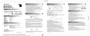
INCLUDED PARTS / HARNESS DETAILS
CONNECTION & ELECTRICAL INFORMATION
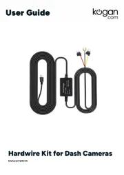
INSTALLATION PROCEDURE CAMERA ADJUSTMENTS
Image view Selectable (Mirror Image as default)
Sensor type High quality CMOS
TV Line resolution 960 TV lines equivalent
Resolution (Pixel) 470,000 pixels
Min. illumination 0.1 Lux~0.01 Lux
Video system NTSC (Color)
Voltage & max. current 9 V DC to 16 V DC, 100 mA
Operation temperature -30°C ~ +70°C
Storage temperature -30°C ~ +85°C
Compliance statement FMVSS 111
Alteration or modifications carried out without appropriate authorization may invalidate the user's
right to operate the equipment.
FEDERAL COMMUNICATIONS COMMISSION SUPPLIER'S DECLARATION OF CONFORMITY
Product Name: Universal Rear-view Camera
Responsible Party Name: PIONEER ELECTRONICS (USA) INC.
Address: 970 W. 190th STREET, SUITE 360, TORRANCE CA90502, USA
URL: http://www.pioneerelectronics.com
28-8, Honkomagome 2-chome, Bukyo-ku, Tokyo 113-0021, JAPAN
PIONEER ELECTRONICS (USA) INC.
P.O. BOX 1540, Long Beach, California 90801-1540, U.S.A.
© 2023 PIONEER CORPORATION
• Installation and wiring of this product require specialist skill and experience.
To assure your safety, please request a specialist technician to install the unit.
• Do not attempt to heat the surface of the camera lens or camera lens itself with a lighter and so on when
they have become frozen. This can cause a malfunction.
• This product is a rear view camera for checking the view at the rear of a vehicle. A rear view camera is a
camera that provides symmetrical images in the same way as rear and side view mirrors.
• This product is designed to supplement the driver’s rear view, but the camera images do not show all
dangers and obstacles. Be sure to look behind you when reversing to confirm the view.
• This product features a wide-angle lens, so the near view is wide and the far view is narrow, which may
create a false sense of distance. Be sure to look behind you when reversing to confirm the view.
• Do not wash your vehicle with an automatic car wash or high-pressure water as it may result in water
entering the camera or the camera falling off.
• Check camera stand installation before driving.
Are the screws loose? Is the camera stand firmly secured?
(If the rear view camera comes loose while you are driving it may cause an accident.)
• This product by itself does not display guidelines.
• System is designed for +12 V DC systems only.
• Be cautious when mounting camera and wiring near fuel tank.
ACC position No ACC position
• This unit is for vehicles with a and . 12-volt battery (DC / ) negative grounding
(Before installing it in a recreational vehicle, truck, or bus, check the battery voltage.)
• To avoid short-circuits in the electrical system, be sure to disconnect the battery cable before installation.
• Refer to the owner’s manual for details on connecting the other units, then make connections correctly.
• Secure the wiring with cable clamps or adhesive tape around them where they lie against metal parts.
Route and secure all wiring so it cannot touch any moving parts, such as the gear shift, parking brake and
seat rails. Do not route wiring in places that get hot, such as near the heater outlet. If the insulation of the
wiring melts or gets torn, there is a danger of the the wiring short-circuiting to the vehicle body.
• Do not shorten any leads.
• Never feed power to other equipment by cutting the insulation of the power supply lead of the unit and
tapping into the lead. The current capacity of the lead will be exceeded causing over heating.
• Please request specialist technician for the replacement of the fuse with correct specification.
• To minimize noise locate the TV antenna cable, radio antenna cable and RCA power supply cable as far
away from each other as possible.
• Connection to a TV with an RCA video input is possible, but confirm whether the TV you use has a reverse
gear connection function.
• If this unit is installed in a vehicle that does not have an ACC (accessory) position on the ignition
switch, the red lead of the unit should be connected to a terminal coupled with ignition ON/OFF
operations. If this is not done, the vehicle battery may be drained when you are away from the vehicle
• Cords for this product and those for other products may be different colors even if they have the same
function. When connecting this product to another product, refer to the supplied manuals of both products
and connect cords that have the same function.
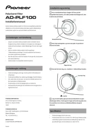
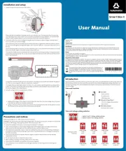
CAMERA INSTALLATION POSITION OPTIONS
The camera mounting base can be positioned either vertically or horizontally.
(Install the rear view camera so that ) the mark is located on the top of camera
Note: Disassembly of the camera mounting bracket may be necessary depending on mounting.
(Be sure not to hide any part of the characters on the licence plate when attaching the camera)
REAR-VIEW / FRONT-VIEW SETTING
For a front-view camera installation, connect the two white wires provided for this purpose.
• Install the unit near the center of the vehicle.
• Locate in the position you want to install the rear view camera.
• Adjust the angle of the rear view camera, and install so that the camera body doesn’t touch the vehicle.
(Avoid touching any sheet metal or glass section from the vehicle)
• Before making a final installation of the unit, temporarily connect the wiring to confirm that the connections
are correct and the system works properly.
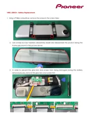
MOUNTING BASE INSTALLATION
1- Clean the surface to which the rear view camera is to be installed.
(Use a cloth or other item to wipe oil, wax, dust and only other dirt from installation surface)
2- Peel off the sheet on the back of the camera stand and stick it on.
3- Press the camera stand with your fingers to stick it to the installation surface.
(Touching the adhesive surface or sticking the unit on a second time reduces adhesive power)
CABLE AND WIRE LEADS ROUTING
• Make sure none of the leads are trapped between this unit and the surrounding metalwork or fittings.
(To protect the wire from a break and short circuit to ground)
• Before drilling any mounting holes always check behind where you want to drill the holes.
(Do not drill into the gas line, brake line, electrical wiring or other important parts)
• Always use protective rubber grommet when wire or cable must pass through sheet metal.
(To protect the wire from a break and short circuit to ground, and to avoid any liquid infiltration)
• If the wiring of this unit is located under a front seat, make sure it does not obstruct seat movement.
(Route all leads and cable carefully around the any mechanisms so they do not get caught or pinched)
1- Route the wire from the camera unit inside the vehicle. When possible, we suggest you use the existing
rubber sleeves to avoid any drilling. The cable is long enough to allow you to bring the connector into
the rear quarter panel of the vehicle.
2- Connect the camera to the power/video cable and route the cable inside the vehicle from the rear of the
vehicle to the display unit and the ACC. +12 V DC power source.
3- Connect the video output RCA connector to the dedicated input of the display unit.
4- Connect the A . +12 V DC wire of the camera (Red wire) as mentioned previously in this document.CC
5- Connect the Ground of the camera (Black wire) to the vehicle body by using the appropriate mechanical
This equipment has been tested and found to comply with the limits for a Class B digital device, pursuant to
Part 15 of the FCC Rules. These limits are designed to provide reasonable protection against harmful
interference in a residential installation. This equipment generates, uses and can radiate radio frequency
energy and, if not installed and used in accordance with the instructions, may cause harmful interference to
radio communications. However, there is no guarantee that interference will not occur in a particular
installation. If this equipment does cause harmful interference to radio or television reception, which can be
determined by turning the equipment off and on, the user is encouraged to try to correct the interference by
one or more of the following measures:
• Reorient or relocate the receiving antenna.
• Increase the separation between the equipment and receiver.
• Connect the equipment into an outlet on a circuit different from that to which the receiver is connected.
• Consult the dealer or an experienced radio/TV technician for help.
This device complies with part 15 of the FCC Rules. Operation is subject to the following two conditions:
(1) This device may not cause harmful interference, and (2) this device must accept any interference
received, including interference that may cause undesired operation.
IMPORTANT NOTES & INSTALLATION TIPS
• Use only the parts included with the unit to ensure proper installation.
(The use of unauthorized parts can cause malfunctions)
• Consult with your nearest dealer if installation requires;
• Any other modifications of the vehicle.
• Install the unit where it does not get in the driver’s way and cannot injure the passenger.
(If there is a sudden stop, like an emergency stop)
• If this unit is installed in the passenger compartment, anchor it securely.
(So it does not break free while the vehicle is moving, and cause injury or an accident)
• Install so that it does not obstruct the rear field of view.
• Install so that it does not protrude from the side of the vehicle.
• Do not perform installation in rain or fog.
• When humidity is high, dry the surface to which the unit is to be attached before installing.
(Moisture on the attachment surface reduces adhesive strength which may lead to the unit coming off)
• If the temperature of the attachment surface is low, warm it with a hair dryer of other means before
installing the camera base to improve adhesive strength.
• Do not attach the camera stand to areas on the vehicle body treated with fluorocarbon resin, or glass.
(This may result in the rear view camera falling off)
• During the 24-hour period after installing:
• Do not apply water to the unit.
• Do not expose the unit to rain.
• Do not subject the camera to unnecessary force.
1- Park the vehicle in a safe place with a typical view to refer to.
2- Secure the vehicle's parking brake.
3- Activate the camera and display unit by turning on the ACC. in the vehicle.
4- Manually activate the reversing camera input of the display.
• Most display units have a dedicated menu for it.
• If required, temporarily connect the display input activation wire to a
+12 V DC source to simulate information from the vehicle's reverse lights.
5- Carefully adjust the position of the camera for an optimal view.
• Camera view must be centered horizontally
• Camera view must be centered vertically
• Any upward alignment, may cause unwanted reflections with the sun.
6- Lock the camera angle using the hex key.