Pulsar AWO317 Manual
Pulsar
Ikke kategoriseret
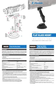
AWO317

| Mærke: | Pulsar |
| Kategori: | Ikke kategoriseret |
| Model: | AWO317 |
Har du brug for hjælp?
Hvis du har brug for hjælp til Pulsar AWO317 stil et spørgsmål nedenfor, og andre brugere vil svare dig
Ikke kategoriseret Pulsar Manualer
15 Oktober 2025
12 Oktober 2025
11 Oktober 2025
11 Oktober 2025

16 September 2025
11 Juli 2025
11 Juli 2025
11 Juli 2025
10 Juli 2025
10 Juli 2025
Ikke kategoriseret Manualer
- Fulgor Milano
- Wachendorff
- Hushmat
- Icarus Blue
- Swan
- Altech UEC
- Ednet
- Neff
- GFB
- SpeakerCraft
- Winston
- Bowers & Wilkins
- KitchenAid
- Toolit
- BBQ Premium
Nyeste Ikke kategoriseret Manualer

16 December 2025

16 December 2025

16 December 2025

16 December 2025

16 December 2025

16 December 2025

16 December 2025

16 December 2025

16 December 2025

16 December 2025