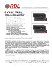
Models RU-VCA2A & RU-VCA6A
Digitally Controlled Attenuators
EXTERNAL CONTROL OPTIONS (SEE ALL RDL REMOTE CONTROL OPTIONS ON THE
RU-VCA2A AND RU-VCA6A PRODUCT PAGES OF THE RDL WEBSITE: www.rdlnet.com)
Inputs (2, RU-VCA2A; 6, RU-VCA6A): >10 k Balanced bridging, or Unbalanced, line level
Frequency Response: 10 Hz to 50 kHz (+/- 0.5 dB)
THD+N: < 0.005% (20 Hz to 20 kHz)
Gain: Adjustable from unity to <–96 dB
Headroom: > 18 dB (above +4 dBu)
Residual Noise: < -90 dB (referred to +4 dBu at unity gain)
CMRR: <-65 dB (50 to 150 Hz)
Crosstalk: <-95 dB (1 kHz, typ.); < -85 dB (20 Hz to 5 kHz); < -75 dB (5 kHz to 20 kHz)
Ramp Times: 0.5 second delay; then: 3 seconds to 10 seconds
(UP and DOWN times individually adjustable on front panel)
Indicators (10): Front-panel LEDs indicating relative audio level (8), MAX condition (green), MIN condition (red)
Audio Output (2, RU-VCA2A; 6, RU-VCA6A): 150 balanced (may be connected unbalanced)
Ramp Output: 0 to 10 Vdc, (Ground-referenced) Note: Not intended to drive additional VCA 0-10V inputs
EQ Ramp Output: 0 to 10 Vdc, (Ground-referenced) Note: dc taper intended only to drive RDL Loudness EQ (ST-LEQ1)
Power Requirement: 24 Vdc @ 120 mA, Ground-referenced (RU-VCA2A); 24 Vdc @ 200 mA, Ground-referenced (RU-VCA6A)
Ambient Operating Environment: 0° C to 50° C
Case Dimensions: 5.75” (14.6 cm) W x 1.65" (4.18 cm) H x 3.54” (9.0 cm) D;3.9" (9.9 cm) D with connectors
Declaration of Conformity available from rdlnet.com.
Sole EMC specifications provided on product package.
Specifications are subject to change without notice.
Radio Design Labs Technical Support Centers
U.S.A. (800) 933-1780, (928) 778-3554; Fax: (928) 778-3506
Europe [NH Amsterdam] (++31) 20-6238 983; Fax: (++31) 20-6225-287
REAR PANEL layouts showing balanced and
unbalanced wiring examples.
Note: The EQ RAMP controls an
RDL ST-LEQ1 for automatic
"loudness" adjustment. See
ST-LEQ1 data sheet for details.
NOTE: This equipment has been tested and found to
comply with the limits for a Class B digital device, pursuant
to part 15 of the FCC Rule. These limits are designed to
provide reasonable protection against harmful interference
in a residential installation. The equipment generates,
uses and can radiate radio frequency energy and, if not
installed and used in accordance with the instructions,
may cause harmful interference to radio communications.
However, there is no guarantee that interference will not
occur in a particular installation. If this equipment does
cause harmful interference to radio or television reception,
which can be determined by turning the equipment off an
on, the user is encouraged to try to correct the
interference by one or more of the following measures:
Reorient or relocate the receiving antenna
Increase the separation between the equipment
Connect the equipment into an outlet on a circuit
different from that which the receiver is
Consult the dealer or an experienced radio/TV
Enable remote control by setting
POWER UP switch 2 to 0 TO 10 VDC
Enable potentiometer control by setting
POWER UP switch 2 to 0 TO 10 VDC
Enable external ramp control by setting
POWER UP switch 2 to 0 TO 10 VDC
MULTIPLE REMOTE LOCATIONS
Enable pushbutton control by setting
POWER UP switch 2 to MOM (momentary)
Enable momentary "pull to ground" control
by setting POWER UP switch 2 to MOM
A VCA module set as MASTER (switch 3) is able to control the level on multiple modules. The EXTERNAL CONTROL
DATA OUT jack provides data to control additional modules. Connect the OUT jack to the IN jack of the first adjacent
module. Connect the OUT jack of the first adjacent module to the IN jack of the second adjacent module. Connect
additional modules in the same manner. Each connected module must be set to SLAVE mode (switch 3) as shown.
(Note: The Power Up CTRL switch must be set to MOM to activate the front-panel buttons.)
LEVEL ADJUSTMENT: Momentarily press the UP or DOWN button to step the level 0.5 dB. Press and hold to
ramp the level up or down.
RAMP TIME: Adjust the TIME controls for the desired ramp rate. (Note: TIME "-" is fastest; TIME"+" is slowest)
GO TO PRESET: Press this button to return the audio level to the stored preset value.
1] Set the audio level to the desired volume using the front-panel (or external) UP and DOWN buttons.
2] Press and hold the GO TO PRESET button (3 seconds) until the front-panel level LED flashes.
OBSERVE AUDIO LEVEL: The relative audio level is displayed on the LED string display. The level is displayed
in both the MOMentary and 0 to 10 VDC operating modes. (Note: The LED string display increments do not
directly correspond to the LED level increments on RDL remote controls.)
Before applying power, set the POWER UP switches:
1 Set to LAST if the module should power-up to the last level setting;
Set to PRESET if the module should power-up to the stored preset
2 Set to MOM (momentary) if module levels are to be adjusted using
front-panel buttons or using buttons, remote controls or open-
collector pulses connected to the rear-panel UP and DN terminals.
3 Set to MASTER if this module is either operating on its own or is
intended to control the level of additional modules; Set to SLAVE if
this module is to be controlled by another module. (Note: The SLAVE
mode inactivates all front and rear panel control of the module.)