Connecting the WT-10 to the cymbal
* To prevent malfunction and equipment failure,
always turn down the volume, and turn o all
the units before making any connections.
Example: mounting onto a WT-10 stand
1. Use the cable included with the WT-10
to connect the hi-hat to the WT-10.
Connect the TRIGGER OUTPUT jack of the VH-10
to the PAD1 jack of the WT-10, and connect
the CONTROL OUTPUT jack of the VH-10 to the
TRIGGER
TRIGGER
TRIGGER
TRIGGER TRIGGER
OUTPUT jack
OUTPUT jack
OUTPUT jack
OUTPUT jackOUTPUT jack
CONTROL
CONTROL
CONTROL
CONTROL CONTROL
OUTPUT jack
OUTPUT jack
OUTPUT jack
OUTPUT jackOUTPUT jack
To
To
To
To
To W
W
W
WT-10
T-10
T-10
T-10WT-10 P
P
P
PAD1
AD1
AD1
AD1 PAD1
(HI-HA
(HI-HA
(HI-HA
(HI-HAT
T
T
T) jack
) jack
) jack
) jack(HI-HAT) jack
To
To
To
To
To W
W
W
WT-10
T-10
T-10
T-10WT-10 P
P
P
PAD2
AD2
AD2
AD2 PAD2
(HH CONTROL) jack
(HH CONTROL) jack
(HH CONTROL) jack
(HH CONTROL) jack(HH CONTROL) jack
Use the cable tie as necessary to hold the cables
Use the connection cable (included with the
WT-10) to connect the cymbal to the WT-10.
Connect the L-shaped plug of the connection cable
BELL OUTPUT
BELL OUTPUT
BELL OUTPUT
BELL OUTPUT BELL OUTPUT
BOW/EDGE
BOW/EDGE
BOW/EDGE
BOW/EDGE BOW/EDGE
OUTPUT jack
OUTPUT jack
OUTPUT jack
OUTPUT jackOUTPUT jack
To
To
To
To
To W
W
W
WT-10
T-10
T-10
T-10WT-10 P
P
P
PAD1
AD1
AD1
AD1 PAD1
(RIDE) jack
(RIDE) jack
(RIDE) jack
(RIDE) jack(RIDE) jack
To
To
To
To
To W
W
W
WT-10
T-10
T-10
T-10WT-10 P
P
P
PAD2
AD2
AD2
AD2 PAD2
(BELL) jack
(BELL) jack
(BELL) jack
(BELL) jack(BELL) jack
Use the cable tie as necessary to hold the cables
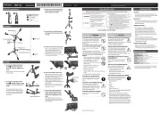
Conguring the cymbal triggers
You can congure the VH-10 and CY-16R-T triggers
and adjust the VH-10 oset on the computer
to which the DrumLink™ wireless USB hub is
See the “DWe Control Setting Guide” (Roland
website) for details on how to congure the
https://www.roland.com/manuals/
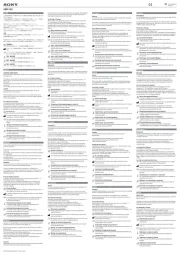
The hi-hat pad can distinguish between a bow shot
(striking the pad face) and edge shot (striking the
edge with the shoulder of your stick).
Edge sensor
Edge sensor
Edge sensor
Edge sensorEdge sensor
The pad can distinguish between strikes in three
dierent zones: bow, bell and edge.
* Bell shots are possible when the connection is
Edge sensor
Edge sensor
Edge sensor
Edge sensorEdge sensor
You can also use the choke technique by grasping
around the edge of the cymbal after you’ve struck
* Choke the location of the edge sensor shown in
the gure. If you choke an area where there is
no sensor, the sound does not stop.
Edge sensor
Edge sensor
Edge sensor
Edge sensorEdge sensor
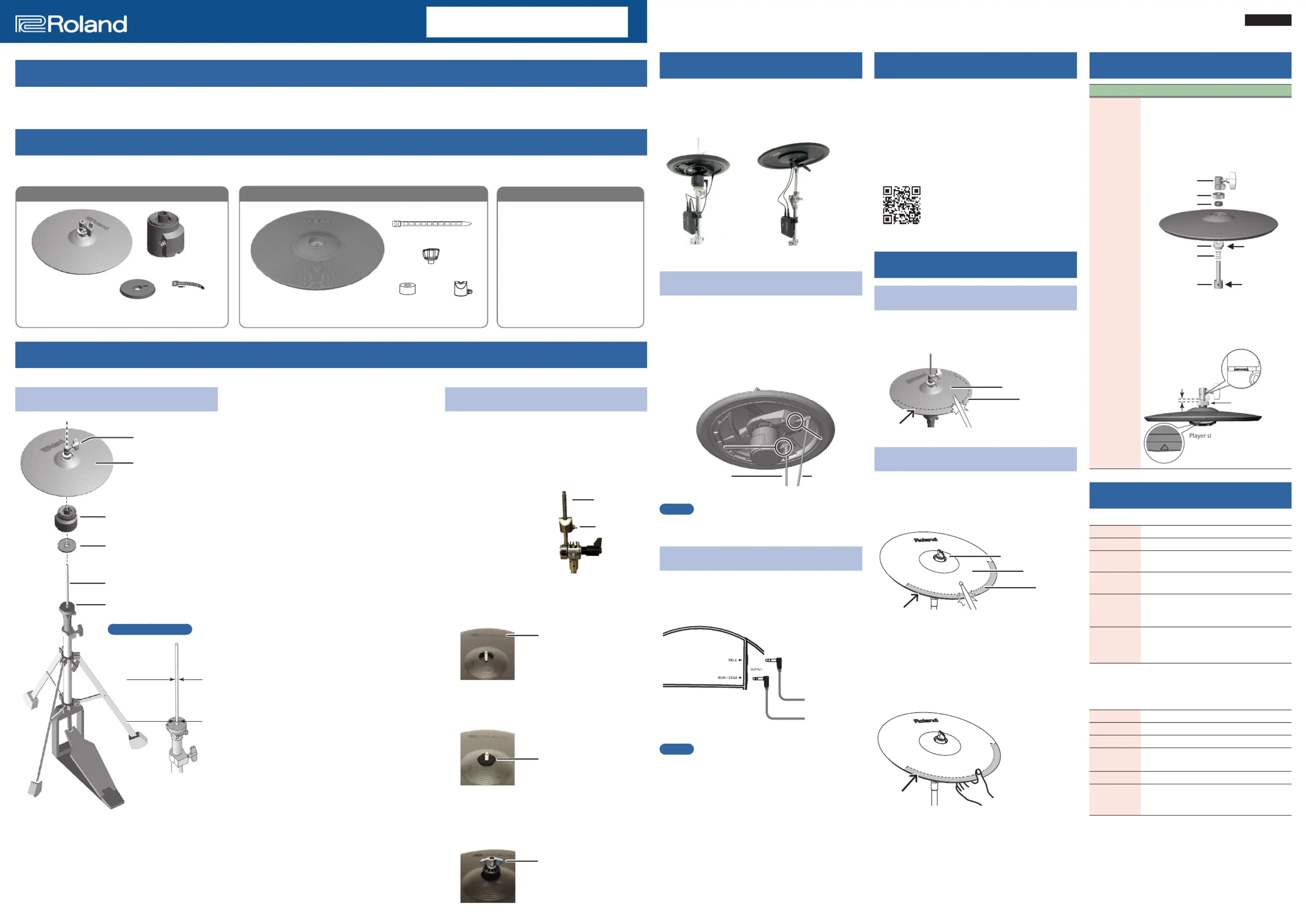
If the hi-hat clutch inadvertently comes o
the hi-hat, refer to the illustration below for
how to reassemble and reattach it.
* The clutch that comes with the hi-hat
stand uses a dierent shape, and can’t be
used with the VH-10. Be sure to use the
clutch that’s made for the VH-10.
Clutch top
Clutch top
Clutch top
Clutch topClutch top
Rubber washer
Rubber washer
Rubber washer
Rubber washerRubber washer
Player side
Player side
Player side
Player sidePlayer side
T
T
T
Top of stopper
op of stopper
op of stopper
op of stopperTop of stopper
Make sure
Make sure
Make sure
Make sure Make sure
the part faces
the part faces
the part faces
the part faces the part faces
correctly
correctly
correctly
correctlycorrectly
Screw should
Screw should
Screw should
Screw should Screw should
face towards the
face towards the
face towards the
face towards the face towards the
player
player
player
playerplayer
Spring
Spring
Spring
SpringSpring
Bottom of stopper
Bottom of stopper
Bottom of stopper
Bottom of stopperBottom of stopper
Oset adjustment
Oset adjustment
Oset adjustment
Oset adjustment Oset adjustment
screw
screw
screw
screwscrew
Roland logo
Roland logo
Roland logo
Roland logoRoland logo
F
F
F
Far side facing
ar side facing
ar side facing
ar side facing Far side facing
away from the
away from the
away from the
away from the away from the
player
player
player
playerplayer
* Orient the protrusions on the top of the
stopper so they align with the grooves on
Oset adjustment
Oset adjustment
Oset adjustment
Oset adjustment Oset adjustment
screw fully tightened
screw fully tightened
screw fully tightened
screw fully tightenedscrew fully tightened
T
T
T
Top of stopper
op of stopper
op of stopper
op of stopper Top of stopper
screw pipe is
screw pipe is
screw pipe is
screw pipe is screw pipe is
visible
visible
visible
visiblevisible
3–4 mm
3–4 mm
3–4 mm
3–4 mm3–4 mm
TRIGGER OUTPUT jack, CONTROL OUTPUT
314 (W) x 314 (D) x 103 (H) mm
12-3/8 (W) x 12-3/8 (D) x 4-1/16 (H) inches
(Excluding motion sensor unit)
Owner’s Manual, Leaet “USING THE UNIT
SAFELY”, Motion sensor unit, Insulating plate,
* The hi-hat’s rubber surface may turn white, but this has no
eect on the hi-hat’s function.
Trigger 3 (Bow, Bell, Edge)
Connectors BELL OUTPUT jack, BOW/EDGE OUTPUT jack
407 (W) x 407 (D) x 56 (H) mm
16-1/16 (W) x 16-1/16 (D) x 2-1/4 (H) inches
Weight 1.3 kg / 2 lbs 14 oz
Owner’s manual, Leaet “USING THE UNIT
SAFELY”, Cymbal nut, Felt washer, Stopper,
* This document explains the specications of the product
at the time that the document was issued. For the latest
information, refer to the Roland website.
The 4CY-4WT-01 is a set that includes a rubber cymbal that reduces the impact sound of the DWe (*) when you strike the cymbal, along with a wireless transmitter.
(*) A convertible drum kit that gives you the enjoyment of playing both acoustic and electronic drums.
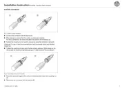
Once you’ve opened the package, make sure that nothing is missing. If any of the included items are missing, consult with the dealer from which you purchased
Refer to the Owner’s Manual
Before using these products, carefully read the “USING THE UNIT SAFELY” and “IMPORTANT NOTES” documents that are included
in each of the product boxes. After reading, keep the document(s) where it will be available for immediate reference.
Clutch screw
Clutch screw
Clutch screw
Clutch screwClutch screw
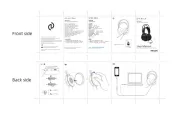
Hi-hat
Hi-hat
Hi-hat
Hi-hatHi-hat
Motion sensor unit
Motion sensor unit
Motion sensor unit
Motion sensor unitMotion sensor unit
CONTROL OUTPUT jack should
CONTROL OUTPUT jack should
CONTROL OUTPUT jack should
CONTROL OUTPUT jack should CONTROL OUTPUT jack should
be on the side facing away from
be on the side facing away from
be on the side facing away from
be on the side facing away from be on the side facing away from
the player
the player
the player
the playerthe player
“
“
“
“Roland
Roland
Roland
Roland”
”
”
” logo should be on
logo should be on
logo should be on
logo should be on “Roland” logo should be on
the farther side away from
the farther side away from
the farther side away from
the farther side away from the farther side away from
the player
the player
the player
the playerthe player
Sponge side up
Sponge side up
Sponge side up
Sponge side upSponge side up
Insulating plate
Insulating plate
Insulating plate
Insulating plateInsulating plate
Cymbal rod
Cymbal rod
Cymbal rod
Cymbal rodCymbal rod
Cymbal rec
Cymbal rec
Cymbal rec
Cymbal receiver
eiver
eiver
eiverCymbal receiver
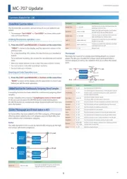
* When turning the VH-10 upside down, protect
the clutch and the sensor from damage. Handle
the unit with care so that it is not dropped or
1. Remove the clutch included with the
hi-hat stand from the cymbal rod.
* The clutch included with the hi-hat stand is not
* You don’t need to remove the cymbal receiver
(the felt or rubber part) from the hi-hat stand.
2. Conrm that the cymbal rod is rmly
For instructions on tightening the cymbal rod,
refer to the Owner’s Manual for your hi-hat
* Looseness or play in the cymbal rod can make
the hi-hat unstable, causing it to shake or turn
and prevent proper functioning.
3. Stick the cymbal rod through the
insulating plate, and place the
insulating plate on top of the cymbal
The sponge side of the insulating plate should
4. Pass the cymbal rod through the hole
on the motion sensor unit.
Position the CONTROL OUTPUT jack on the
farther side, as viewed from the player.
5. Loosen the clutch screw and pass the
hi-hat through the cymbal rod.
The hi-hat should be oriented correctly. Position
the Roland logo on the farther side as viewed
from the player to obtain the best sensitivity.
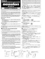
* The cymbal nut included with the CY-16R-T is not
used. You must use the cymbal nut included with
the stand to tighten, due to the dierence in size.
1. Remove the parts from the cymbal
stand that are used to stabilize the
3. Mount the cymbal so that the Roland
logo is on the far side facing away
Roland logo
Roland logo
Roland logo
Roland logoRoland logo
F
F
F
Far side facing away from the
ar side facing away from the
ar side facing away from the
ar side facing away from the Far side facing away from the
player
player
player
playerplayer
4. Pass the cymbal rod through the felt
washer included with the CY-16R-T.
Felt washer
Felt washer
Felt washer
Felt washerFelt washer
(made by Roland)
(made by Roland)
(made by Roland)
(made by Roland)(made by Roland)
5. Tighten the cymbal nut included
with the stand to get the appropriate
Cymbal nut included with stand
Cymbal nut included with stand
Cymbal nut included with stand
Cymbal nut included with standCymbal nut included with stand
Cymbal rod
Cymbal rod
Cymbal rod
Cymbal rodCymbal rod
Stopper
Stopper
Stopper
StopperStopper
(made by Roland)
(made by Roland)
(made by Roland)
(made by Roland)(made by Roland)
Diameter: 6.0–7.0 mm
Diameter: 6.0–7.0 mm
Diameter: 6.0–7.0 mm
Diameter: 6.0–7.0 mmDiameter: 6.0–7.0 mm
Diameter: 11.7 mm max.
Diameter: 11.7 mm max.
Diameter: 11.7 mm max.
Diameter: 11.7 mm max.Diameter: 11.7 mm max.