Roland M-10MX Manual
Roland
Blandekonsol
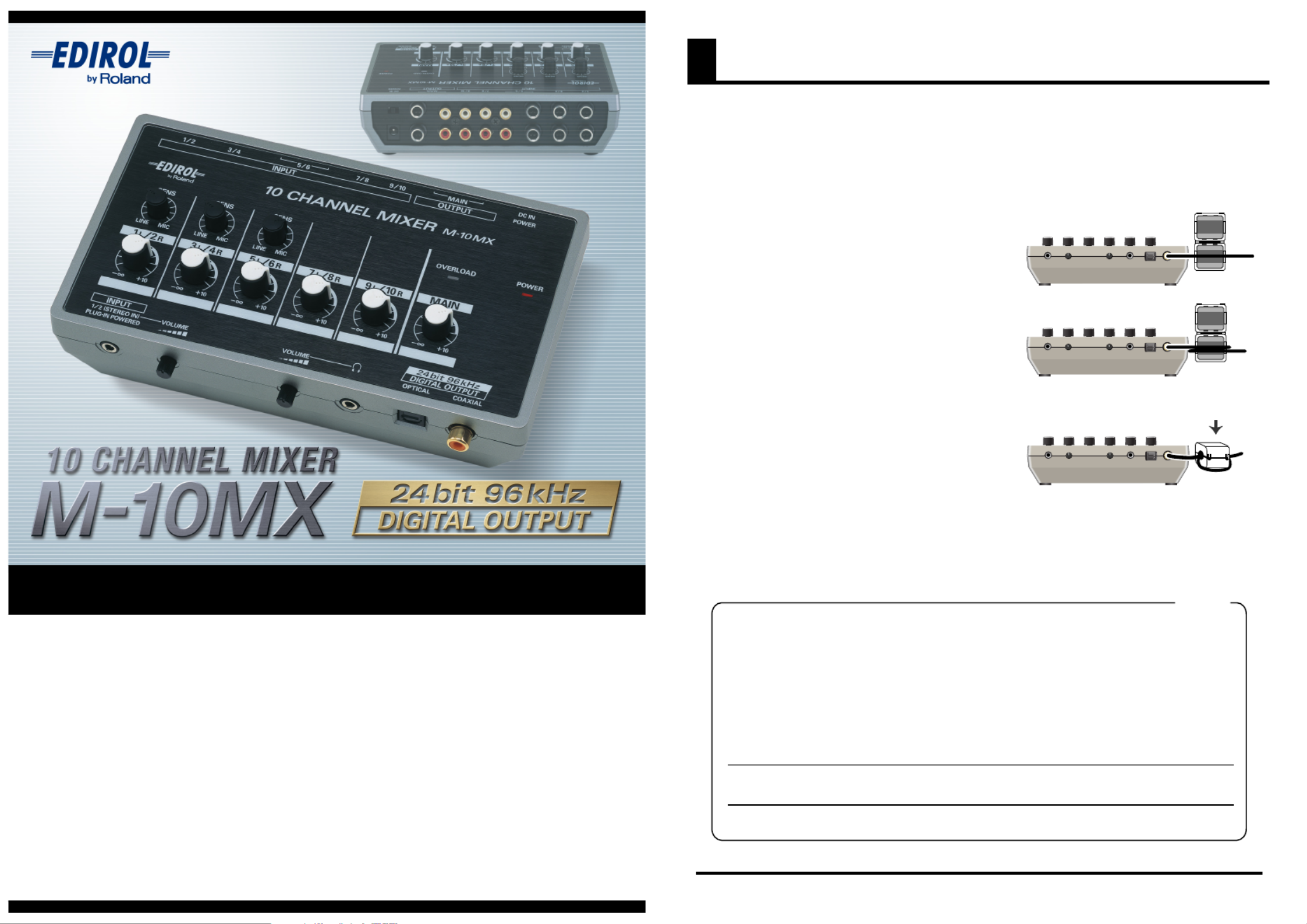
M-10MX
| Mærke: | Roland |
| Kategori: | Blandekonsol |
| Model: | M-10MX |
Har du brug for hjælp?
Hvis du har brug for hjælp til Roland M-10MX stil et spørgsmål nedenfor, og andre brugere vil svare dig
Blandekonsol Roland Manualer
30 August 2024

28 Juli 2024

28 Juli 2024

25 Juli 2024
Blandekonsol Manualer
- Auna
- Heritage Audio
- Vonyx
- Allen-Heath
- Klark Teknik
- Stanton
- Primo
- TeachLogic
- Pyle
- Philips
- Rolls
- Nektar
- Koda
- M-GAME
- Hobart
Nyeste Blandekonsol Manualer

3 April 2025
19 Marts 2025
5 Marts 2025

27 Februar 2025

12 Februar 2025
10 Februar 2025

15 Januar 2025

15 Januar 2025

15 Januar 2025

11 Januar 2025