02-2302 2040 6014
− 1 − − 2 − − 3 − − 4 − − 5 −
[1]
SAFETY PRECAUTIONS
*Before use, read the following safety
precautions.
This instruction manual explains how to use
your digital clamp meter DCM301. Before use,
please read this manual thoroughly to ensure
correct and safe use. After reading it, keep it
together with the product for reference to it
when necessary.
Using the product in a manner not specified in
this manual may cause damage to the protection
function of the product.
The instructions given under the headings of
WARNING and
CAUTION must be followed
to prevent accidental burn and electric shock.
1-1 Explanation of Warning Symbols
The meanings of the symbols used in this
manual and attached to the product are as
follows:
: Very important instructions for safe use.
•
The warning messages are intended to
prevent accidents to operating personnel
such as burn and electric shock.
•
The caution messages are intended to
prevent incorrect handling which may
damage the product.
: High voltage hazard : Ground
: Resistance : Buzzer
: Light : Capacitor
: Double insulation or reinforced insulation
1-2 Warning Messages for Safe Use
The following instructions are intended to
prevent personal injury such as burn and
electric shock.
Be sure to follow them when using the meter.
1. This is a clamp meter for low-voltage
circuits. Never use it on a power line that
exceeds 1000 Vrms voltage to ground.
2. Voltages over AC 30 Vrms (42.4 Vpeak)
or DC 60 V are hazardous to human
body. Take care so as not to touch them.
3. Never input signals exceeding the
maximum rated input value (see 1-3).
4. Never use the meter near equipment
which generates strong electromagnetic
waves or is charged.
5. Never use the meter if the meter or test
leads are damaged or broken.
6. Never use the meter with the case or
battery lid removed.
7. During measurement, keep your fingers
behind the finger guard of test leads
and the barrier of the meter.
8. During measurement, do not change
function switch of the meter.
9. Before starting measurement, make
sure that the function and range are
properly set.
10. Never use the meter when it is wet or
with wet hands.
11.
Be sure to use the specified type of test leads.
12. Never attempt repair or modification,
except for battery replacement.
13. Always conduct start-up inspection and
check the meter at least once a year.
14. This meter is for indoor use only.
1-3 Maximum Overload Protection Input
The maximum rated input value and overload
protection have been established for the input
terminals of each function.
Function
Signal Input
Terminal
Max. Rated
Input Value
Max. Overload
Protection
ACA
Clamp type
current
sensor (CT)
AC
1000 Arms
AC
1000 Arms
, ,
Between +
and –
terminals
Do not input
voltage
DC/AC
1000 Vrms
ACV,
DCV, EF
DC/AC
1000 Vrms
[2] APPLICATIONS AND FEATURES
2-1 Applications
This is a digital AC clamp meter designed for
measurement of low-voltage circuits in the
application range of 1000 V CAT. III, 600 V CAT.
IV. It is suited to current and voltage measurement
of power lines, electrical equipment, and electrical
facilities less than 1000 Vrms to ground.
2-2 Features
•
The CT shape makes it easier to clamp cable
in crowded.
•
Complies with IEC61010 CAT. IV and can
measure up to 1000 A AC for use in various sites.
•
True RMS reading for measurement of even
distorted waveforms.
•
An electric field (EF) function is incorporated
in the tip of the CT to enable detection of
about AC 90V or more.
•
Clamp opening diameter of 34 mm at maximum.
•
Large, easy-to-press HOLD button.
•
Equipped with LCD backlight convenient for
measurement in dark places. Also incorporates an
LED light to illuminate the measurement target.
Measurement categories (Overvoltage
categories)
CAT. II :
Primary circuit of equipment with a power
cord to be connected to a mains socket.
CAT.III :
Primary circuit of equipment that inputs power
directly from the distributor and the circuit
from the distributor to the mains socket.
CAT.IV :
Circuit from the leading wire to the distributor.
[3] NAMES OF COMPONENT UNITS
3-1 Main unit
3-2 Display
HOLDAUTO
AC
DC
3-3 Test Lead
In case of test pins cover attached:
CAT.IV 600 V, CAT.III 1000 V
In case of test pins cover removed:
CAT.II 1000 V
[4] DESCRIPTION OF FUNCTION
4-1 Power Switch and function switch
(for all functions)
Turn this switch to turn on and off the power
and select a measuring function.
4-2 Data Hold function: HOLD button
(for functions except EF)
When the HOLD button is pressed, the reading
indicated will be held with
on the
display. The indicated reading will not change if
the input signal is changed. When this button is
pressed again, the function will be disabled and
the meter will return to the measurement mode.
Remarks:
•
The function will be canceled at changing
measurement functions.
4-3 LIGHT function:
Light button
Press the LIGHT button to turn on the display’s
backlight and the LED light. Press it again to
turn them off. The lights will go off automatically
after 30 seconds.
4-4
How to select the measurement function:
SELECT button (ACA,
, ACV)
Press the SELECT button to cycle through the
functions in the order shown below.
ACA
:
ACA → Hz → ACA
:
→ →
ACV
:
ACV → Hz → ACV
4-5 Range Hold function:
RANGE HOLD button (ACA,
, ACV, DCV)
Press the RANGE HOLD button to enter the
Manual mode and set the range (
AUTO
in the
display disappears). In the Manual mode, the
range changes every time this button is pressed.
Select the appropriate range while checking the
displayed unit and position of the decimal point
in the digits. To restore the Auto Range mode,
press and hold this button for more than 1
second (
AUTO
is displayed in the display).
4-6
Relative function:
RELATIVE button (ACA,
, ACV, DCV)
Press the RELATIVE button; “ ” will be
displayed in the display and the digits will show
a relative value — which is derived from the
input value when the button is pressed set at 0
(reference). Press the button again to cancel
this function.
4-7 AUTO POWER OFF function
The meter will go to AUTO POWER OFF function
to save battery life about 10 minutes after the
last function switch or button operation. To wake
up the meter, press any button or re-power on.
turns on while activating the function.
Remarks:
•
Even in the AUTO POWER OFF mode, the tiny
power is still consumed. When the meter is not
going to be used for an extended period of
time, be sure to turn off the power switch.
•
To disable the function, turn on the power of
meter while holding the SELECT button
pressed.
on the display is turned off when
the AUTO POWER OFF function is disabled.
4-8 Low Battery indication
When the built-in batteries have been
discharged and the voltage has dropped to
below about 3.6 V,
appears on the display.
When the mark flickers or lights, replace both
three batteries with new ones.
[5] MEASURING PROCEDURE
5-1 Start-up Inspection
Always perform the following start-up
inspection to ensure safety.
•
External appearance: Make sure that there
are no visible abnormalities on the meter that
may have been caused by dropping it or
other mishandling.
•
Accessories: Make sure that the test leads
and other accessories are free from
breakage, cracks, or any damage.
•
Make sure that the low battery indication is
not displayed in the display. If
is
displayed, replace the batteries with new
ones. Before first use, install the batteries.
•
Make sure that neither the meter nor your
hand is wet.
* If nothing is displayed in the display, the
batteries may be drained.
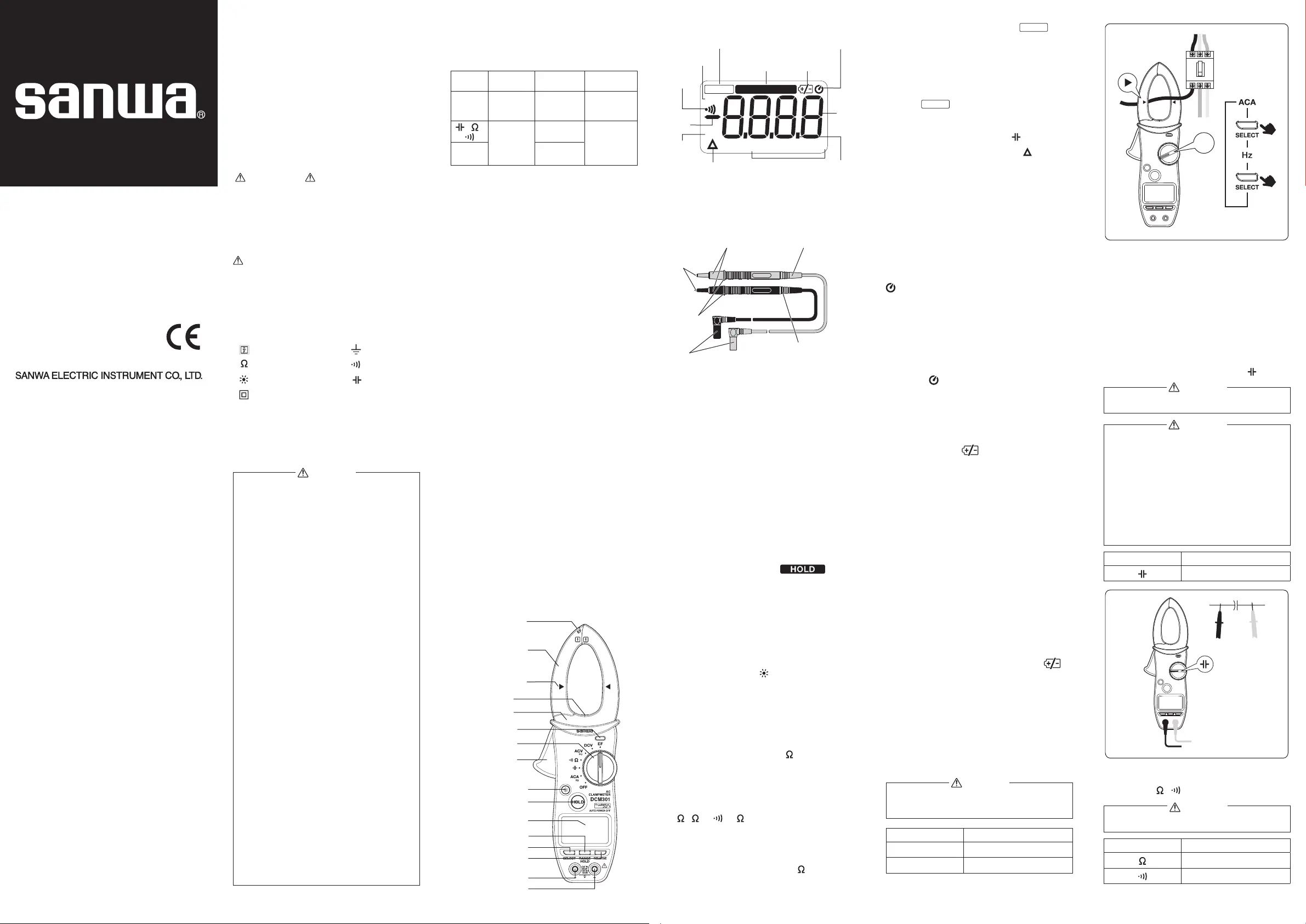
5-2 AC Current / Frequency Measurement:
ACA / Hz
Remove the test leads from the measuring
terminals to avoid electric shock.
Function Max. Rated Input Value
ACA 1000 A
Hz 2 kHz
DIGITAL CLAMP METER
INSTRUCTION MANUAL
DCM301
AC
A
Remarks:
•
Clamp the conductor (cable) to measure in the
middle of the center position mark on the CT.
•
Clamp only one cable. If several cables are
clamped together or duplex, triplex or
quadruplex cable are clamped, current
cannot be measured accurately.
•
The meter may malfunction in places where a
strong magnetic field is present.
•
Do not apply voltage and current at the same time.
5-3 Capacitance Measurement:
Never apply a voltage to the input terminals.
1. Discharge the capacitors before
measurement.
2. This meter uses a measurement method
that applies currents to the measured
capacitor. It is not suitable for measurement
of electrolytic capacitors with high leakage
currents since errors will be too large.
3. It takes longer to measure capacitors with
large capacitance.
Function Max. Rated Input Value
60.00 mF
+
−
5-4 Resistance Measurement, Continuity
Check:
・
Never apply a voltage to the input terminals.
Function Max. Rated Input Value
60.00 MΩ
600.0 Ω
Dempa Bldg
.
, 4-4 Sotokanda 2-Chome Chiyoda-ku, Tokyo, Japan
- MEMO -
WARNING
WARNING
WARNING
CAUTION
WARNING
AUTO RANGE
AC
Continuity
check
Polarity
(-)
Decimal
point
Digit
DC
Relative value UNIT
DATA HOLD
Removal test pins cover
Test probe(red)
Test probe(black)
Test pins
Finger
guards
Plugs
Low battery
indication
AUTO POWER OFF
Clamp type current
sensor (CT)
LED light
Center position mark
Electric Field (EF)
sensor position mark
Power /
Function switch
EF detection LED
Barrier
CT trigger
Light button
HOLD button
Display
RANGEHOLD button
SELECT button
RELATIVE button
Input Terminal ( - )
Input Terminal (+)


