Satel ASD-110 Manual
Læs gratis den danske manual til Satel ASD-110 (4 sider) i kategorien Røgdetektor. Denne vejledning er vurderet som hjælpsom af 40 personer og har en gennemsnitlig bedømmelse på 4.3 stjerner ud af 20.5 anmeldelser.
Har du et spørgsmål om Satel ASD-110, eller vil du spørge andre brugere om produktet?
Produkt Specifikationer
| Mærke: | Satel |
| Kategori: | Røgdetektor |
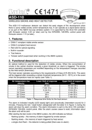
| Model: | ASD-110 |
| Kode for international beskyttelse (IP): | IP20 |
| Højde: | 61 mm |
| Vægt: | 170 g |
| Produktfarve: | Hvid |
| Batterispænding: | 3 V |
| Driftstemperatur (T-T): | 0 - 55 °C |
| Forbindelsesteknologi: | Ledningsført |
| Strømkilde: | Batteri |
| Monteringstype: | Overflademonteret |
| Nem at installere: | Ja |
| Batterilevetid: | 2 År |
| Diameter: | 108 mm |
| Batteritype: | CR123A |
| Understøttet placering: | Horisontal/vertikal |
Har du brug for hjælp?
Hvis du har brug for hjælp til Satel ASD-110 stil et spørgsmål nedenfor, og andre brugere vil svare dig
Røgdetektor Satel Manualer
Røgdetektor Manualer
- ETiger
- REV
- Blaupunkt
- H-Tronic
- Egardia
- Flamingo
- Qolsys
- Mircom
- FirstAlert
- Clas Ohlson
- Fito Profi-line
- WisuAlarm
- Jemay
- Hager
- Gewiss
Nyeste Røgdetektor Manualer