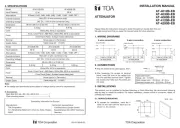
TOA AT-4030B-EB Manual

TOA Ikke kategoriseret AT-4030B-EB

Læs gratis den danske manual til TOA AT-4030B-EB (2 sider) i kategorien Ikke kategoriseret. Denne vejledning er vurderet som hjælpsom af 5 personer og har en gennemsnitlig bedømmelse på 4.9 stjerner ud af 3 anmeldelser. Har du et spørgsmål om TOA AT-4030B-EB, eller vil du spørge andre brugere om produktet?

Side 1/2
2. CONNECTIONS
1. WIRING DIAGRAMS
Please follow the instructions manual to obtain the optimum results from this unit.
We also recommend that you keep this manual handy for future reference.
2-wire connection 3-wire connection 4-wire connection
4. SPECIFICATIONS
Model
Attenuations
Input Capacity
Override Indicator
Overriding Voltage
Dimensions
Weight
Color
Finish
AT-4012B-EB AT-4030B-EB
AT-4060B-EB
12 W
30 W
60 W
8 Steps ( 0 dB, -3dB, -6dB, -9dB, -12dB, -15dB, -18dB, OFF )
Red LED (4-wire connection only)
24V DC, 11mA (4-wire connection only)
86 (w) x 86 (h) x 52 (d) mm
86 (w) x 86 (h) x 79 (d) mm
White (RAL 9016 or equivalent)
Knob, Cover Panel : ABS Resin, White (RAL 9016 or equivalent)
Note:
The design and specifications are subject to change without notice for improvement.
Accessories
Back Box 85.5 (w) x 85.5 (h) x 60 (d) mm ................. 1
Plate mounting screw ............................................... 2
This product can be installed by Surface Mounting or Flush Mounting. We recommend following
step by step to install this product. For better installation, please consult a contractor, dealer, or
professional installer.
3.1. SURFACE MOUNTING
3. INSTALLATIONS
55
55
4 holes
WALL
Applicable cable :
Range : 22 - 14 AWG
Solid copper wire : 0.6mm - 1.6mm
Stranded copper wire : 0.8mm - 2mm
Unit : mm
Strip the shield of the cable approx. 9mm.
After loosening the screws at terminal
block, insert the core of the cables fully
into the specified terminal block. Tighten
the screws and make sure the cables are
not loose.
To prepare for installation, mark the 4
holes on the wall with the back box as
shown in the picture.
Hot In
COM
approx. 9 mm
Cable
Core
N.C N.C
Hot In
COM
Note : N.C is NOT CONNECTED
Terminal
Usable Cable
Cable range 22 - 14 AWG
Screw type x 5 ( Terminals )
Front Panel (Plate) : Surface treated steel plate
0.12 kg
0.45 kg
0.46 kg
Model
Attenuations
Input Capacity
Override Indicator
Overriding Voltage
Dimensions
Weight
Color
Finish
AT-4120B-EB AT-4200B-EB
120 W
200 W
8 Steps ( 0 dB, -3dB, -6dB, -9dB, -12dB, -15dB, -18dB, OFF )
Red LED (4-wire connection only)
86 (w) x 86 (h) x 79 (d) mm
White (RAL 9016 or equivalent)
Knob, Cover Panel : ABS Resin, White (RAL 9016 or equivalent)
Terminal
Usable Cable
Cable range 22 - 14 AWG
Screw type x 5 ( Terminals )
Front Panel (Plate) : Surface treated steel plate
0.48 kg 0.49 kg
AT-4012B-EB
ATTENUATOR
INSTALLATION MANUAL
Traceability Information for Europe
Manufacturer:
TOA Corporation
7-2-1,
Minatojima-Nakamachi, Chuo-ku, Kobe, Hyogo,
Japan
Authorized representative:
TOA Electronics Europe GmbH
Suederstrasse 282, 20537 Hamburg,
Germany
24V DC, 11mA (4-wire connection only)
AT-4030B-EB
AT-4060B-EB
AT-4120B-EB
AT-4200B-EB
133-05-00045-00
Screw M3 X 20
Cover Panel
Main unit attenuator
3.2. FLUSH MOUNTING
Flush mounting installation can be implemented in 2 ways, with back box or without back box.
3.2.1 FLUSH MOUNTING WITH BACK BOX
3.2.2 FLUSH MOUNTING WITHOUT BACK BOX
Install the back box with suitable
screws on the surface of the wall.
Connect the recommended cable to
the terminal.
WARNING :
Do not supply 24V DC when connect-
ing 4-wire attenuator system.
Install the main unit to the back box.
Attach the cover panel to the main
unit attenuator until the hook mount
clips perfectly.
Cut this area for
the lane cables.
Step 1.
Step 2.
Step 3.
Step 4.
Unit : mm
65 - 70
69 - 73
WALL
To prepare for installation, mark the
opening on the wall with rectangular
pattern as shown in the picture.
Install the back box inside the wall.
Connect the recommended cable to
the terminal.
WARNING :
Do not supply 24V DC when connect-
ing 4-wire attenuator system.
Install the main unit to the back box.
Attach the cover panel to the main
unit attenuator until the hook mount
clips perfectly.
Step 1.
Step 2.
Step 3.
Step 4.
Cover Panel
Screw M3 X 20
Main unit Attenuator
Support
To prepare for installation, mark the
opening on the wall as shown in the
picture. This mounting method can be
used for all models.
Make opening on the wall.
Connect the recommended cable to
the terminal.
WARNING :
Do not supply 24V DC when
connecting 4-wire attenuator
system.
Install the main unit directly to the
wall using screws that are suitable
for the kind of wall.
Attach the cover panel to the main
unit attenuator until the hook mount
clips perfectly.
Step 1.
Step 2.
Step 3.
Step 4.
57 - 60
72
34.5 - 36.5
36
2 holes
WALL
Cover Panel
Screw
Main unit Attenuator
69 - 73
Unit : mm
Back Box
Support
4
1
2
3
2
4
3
1
2
4
3
1
Cut this area for
the lane cables.


Produkt Specifikationer

Mærke: TOA
Kategori: Ikke kategoriseret
Model: AT-4030B-EB

Har du brug for hjælp?

Hvis du har brug for hjælp til TOA AT-4030B-EB stil et spørgsmål nedenfor, og andre brugere vil svare dig


Ikke kategoriseret TOA Manualer

TOA

TOA HS-150B Manual

10 Oktober 2025
TOA

TOA AT-4030B-EB Manual

10 Oktober 2025
TOA

TOA VX-030DA Manual

10 Oktober 2025
TOA

TOA RS-481 Manual

10 Oktober 2025
TOA

TOA AT-4200B-EB Manual

10 Oktober 2025
TOA

TOA HY-TR1 Manual

10 Oktober 2025
TOA

TOA MD-210CTU-EB Manual

10 Oktober 2025
TOA

TOA HS-120W Manual

10 Oktober 2025
TOA

TOA VX-3000DA Manual

10 Oktober 2025
TOA

TOA AT-4012B-EB Manual

10 Oktober 2025

Ikke kategoriseret Manualer

Nyeste Ikke kategoriseret Manualer

Miele

Miele WTV 511 Manual

10 Oktober 2025
Miele

Miele WTV 601 Manual

10 Oktober 2025
Miele

Miele GaLa-S Manual

10 Oktober 2025
Oras

Oras Saga 3970 Manual

10 Oktober 2025
Xerox

Xerox DocuShare Manual

10 Oktober 2025
Cleanmaxx

Cleanmaxx 03819 Manual

10 Oktober 2025
Furuno

Furuno TZTF19F Manual

10 Oktober 2025
Oras

Oras Hydra 231042 Manual

10 Oktober 2025