TOA VX-3000CT Manual
Læs gratis den danske manual til TOA VX-3000CT (130 sider) i kategorien Ikke kategoriseret. Denne vejledning er vurderet som hjælpsom af 14 personer og har en gennemsnitlig bedømmelse på 4.6 stjerner ud af 7.5 anmeldelser.
Har du et spørgsmål om TOA VX-3000CT, eller vil du spørge andre brugere om produktet?
Produkt Specifikationer
| Mærke: | TOA |
| Kategori: | Ikke kategoriseret |
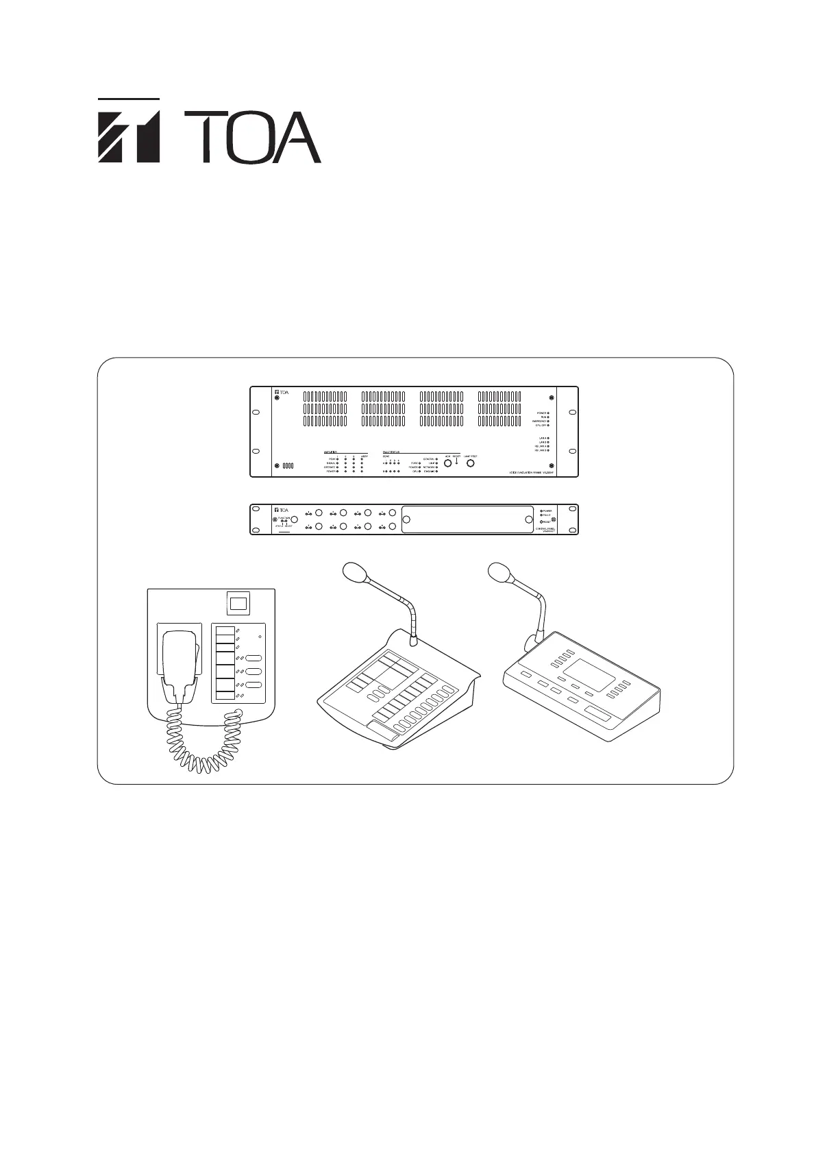
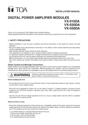
| Model: | VX-3000CT |
| Type: | Kontrolpanel |
| Bredde: | 482 mm |
| Dybde: | 315.2 mm |
| Højde: | 44 mm |
| Vægt: | 3000 g |
| Antal pr. pakke: | 1 stk |
| Produktfarve: | Sort |
| Relativ luftfugtighed ved drift (H-H): | 0 - 90 % |
| Ethernet LAN-porte (RJ-45): | 2 |
| Strømforbrug (typisk): | - W |
| Driftstemperatur (T-T): | 0 - 40 °C |
| Husmateriale: | Stål |
| Strømkilde: | DC |
| Indgangsspænding: | 20 - 33 V |
| Monteringssæt: | Ja |
| Husets farve: | Sort |
| Antal RJ-45-porte: | 2 |
| Strøm (maks.): | 0.11 A |
Har du brug for hjælp?
Hvis du har brug for hjælp til TOA VX-3000CT stil et spørgsmål nedenfor, og andre brugere vil svare dig
Ikke kategoriseret TOA Manualer


Ikke kategoriseret Manualer
- Cherry
- Gasmate
- Tiptop Audio
- Avtec
- Osann
- Creamsource
- Emerson
- COLBOR
- Everpure
- Bluebird
- Clarke
- Sacrament
- SSV Works
- Southern Pride
- Balance
Nyeste Ikke kategoriseret Manualer


