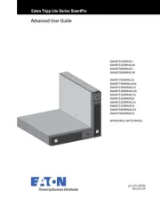
Tripp Lite SmartPro SMART1524ET Manual


Læs gratis den danske manual til Tripp Lite SmartPro SMART1524ET (56 sider) i kategorien Uafbrydelig strømforsyning (UPS). Denne vejledning er vurderet som hjælpsom af 9 personer og har en gennemsnitlig bedømmelse på 4.5 stjerner ud af 5 anmeldelser. Har du et spørgsmål om Tripp Lite SmartPro SMART1524ET, eller vil du spørge andre brugere om produktet?

Side 1/56
1
Owner’s Manual
UPS Systems
Models: SMART1524ET and SMART1548ET
(Series Number: AG-88E6, AG-88E5)
WARRANTY REGISTRATION
Register your product today and be
automatically entered to win an ISOBAR®
surge protector in our monthly drawing!
tripplite.com/warranty
1111 W. 35th Street, Chicago, IL 60609 USA • tripplite.com/support
Copyright © 2020 Tripp Lite. All rights reserved.
Este manual esta disponible en español en la página de Tripp Lite: tripplite.com
Ce manuel est disponible en français sur le site Web de Tripp Lite : tripplite.com
20-10-334 93-397B.indd 1
2
Table of Contents
Important Safety 3
Instructions
UPS Location Warnings 3
UPS Connection Warnings 3
Equipment Connection Warnings 3
Battery Warnings 4
UPS and Battery Recycling 4
Introduction 5
System Architecture 5
Package Contents 6
Optional Accessories 6
User Supplied Items 6
Features 7
UPS Front Panel 7
Mounting 10
2-Post Rack Mounting the UPS 10
4-Post Rack Mounting the UPS 10
Desktop Mounting the UPS 11
Wiring the UPS 12
AC Input and Output Wiring 12
External Battery Connections 13
(Deep-Cycle Lead-Acid
Batteries Only)
Additional Wiring Connections 14
(Optional)
Operation 15
Basic On/Off and Manual 15
UPS Test Verification
Operating the LCD / LED 17
Control Panel
LCD Menu Tree 18
LCD Menu Overview 18
LCD Menu Explanations 19
RS-232 / USB Communications 26
Interface
HyperTerminal Set Up 26
RS-232 / USB Main Menu 30
RS-232 / USB Menu Tree 31
Menu Overview 31
Troubleshooting 45
Alarm and Fault Messaging 45
UPS Alarm Messages 46
Battery Back-Up Time 49
Internal Fan Relacement 50
Fan Replacement 50
Fan Filter Replacement 52
Storage and Service 53
Product Registration 53
Regulatory Compliance 54
20-10-334 93-397B.indd 2
3
Important Safety Instructions
SAVE THESE INSTRUCTIONS
This manual contains instructions and warnings that should be followed
during the installation, operation, maintenance and storage of the UPS and
batteries. Failure to heed these warnings may affect the warranty.
UPS Location Warnings
Install your UPS within an enclosure or location that protects against excessive
moisture, conductive contaminants, dust or direct sunlight.
For best UPS performance, maintain site temperature between -40ºF and 176ºF
(-40ºC and 80ºC).
Leave adequate space around all sides of the UPS for proper ventilation.
Only set the UPS upright on a sturdy flat surface. Do not block fans or ventilation
holes, as this will seriously inhibit the unit’s internal cooling and cause product
damage not covered under warranty.
UPS Connection Warnings
Hardwire the UPS directly to a properly grounded power source.
If the UPS receives power from a motor-powered AC generator, the generator must
provide clean,ltered, computer-grade output.
The mains power that supplies power to the UPS should be easily accessible and
located near the UPS.
Equipment Connection Warnings
Install in accordance with National Electrical Code standards ANSI/
NFPA 70 and Canadian Electrical Code, Part I, C22.1.
Short-circuit backup protection and overcurrent protection is provided
by the building installation.
To reduce the risk of fire, connect only to a circuit provided with
branch circuit overcurrent protection in accordance with the National
Electrical Code, ANSI/NFPA 70 and the Canadian Electrical Code,
Part I, C22.1. Be sure to provide a disconnect device in the end use
installation.
Use of this equipment in life support applications where failure of this equipment
can reasonably be expected to cause the failure of the life support equipment or to
signicantly affect its safety or effectiveness is not recommended.
Do not connect surge protectors or extension cords to the output of your UPS. This
might damage the UPS and may affect the surge protector and UPS warranties.
20-10-334 93-397B.indd 3
4
Important Safety Instructions
Connect the UPS to a power source that is adequately protected against excess
currents, short circuits and earth faults as part of the building installation.
Battery Warnings
Batteries can present a risk of electrical shock and burn from high short-circuit
current. Observe proper precautions. There are no user-serviceable parts inside
the UPS. Do not open the UPS. Do not open batteries. Do not short or bridge the
battery terminals with any object. Do not dispose of batteries in a fire. The batteries
may explode. Released material is harmful to the skin and eyes. It may be toxic.
Unplug and turn off the UPS before performing battery replacement. Use tools with
insulated handles. Battery replacement should be performed only by authorized
service personnel using the same number and type of batteries (sealed lead-acid).
CAUTION: A battery can present a risk of electrical shock and high
short-circuit current. Contact with any part of a grounded battery
can result in electrical shock. The following precautions should be
observed when working on batteries:
Remove watches, rings or other metal objects.
Use tools with insulated handles.
Wear rubber gloves and boots.
Do not lay tools or metal parts on top of batteries.
Disconnect charging source and load prior to installing or maintaining the battery.
Remove battery grounds during installation and maintenance to reduce likelihood
of shock.
Remove the connection from ground if any part of the battery is determined to be
grounded.
UPS and Battery Recycling
Tripp Lite products use sealed lead-acid batteries, which are highly recyclable.
Call Tripp Lite at 773.869.1234 or visit tripplite.com/support/recycling-
program for more information on recycling the batteries or any other
Tripp Lite product. Please refer to local codes for disposal requirements.
20-10-334 93-397B.indd 4
5
Introduction
Tripp Lite’s SMART1524ET and SMART1548ET line-interactive UPS Systems offer a
wide operating temperature range and provide constant and reliable backup power
to critical equipment in harsh environments, including outdoor equipment. The UPS
systems distribute utility power to connected equipment when input power is available
and is within valid UPS voltage limits. Automatic Voltage Regulation (AVR) is available
to stabilize output voltage to protected equipment. The UPS will switch to battery
backup power during utility power outages and extreme voltage fluctuations to keep
connected equipment running without interruption.
The maximum output capacity of the UPS system is temperature-dependent:
1600W: -40°F to 131°F (-40°C to 55°C)
1200W: 131°F to 167°F (55°C to 75°C)
1000W: 167°F to 176°F (75°C to 80°C).
System Architecture
To Remote
Network
Connection
To User’s PC
Note: The 48V configuration is shown for SMART1548ET.
20-10-334 93-397B.indd 5
6
Package Contents
Note: If the listed parts on your package do not match the items you received, or if any items
appear damaged, please immediately notify your carrier agent and the supplier who prepared
your shipment.
Optional Accessories
WEBCARDLXMINI: Network interface card for SNMP/Web control and monitoring
User Supplied Items
Wide Temperature Range 48V DC (SMART1548ET) or 24 VDC (SMART1524ET)
Lead-Acid Battery System with included ANDERSON PA75 DC Connection kit.
The UPS requires a user-supplied battery system that connects to the UPS via
ANDERSON PA75 DC Connection Kit.
The batteries used must be rechargeable, deep-cycle lead-acid type.
Select batteries that meet your high- and low-temperature requirements for
reliable operation.
The recommended battery cable gauges are 6 AWG for the SMART1524ET and
8 AWG for the SMART1548ET, with a maximum recommended length of 6.56 ft. / 2 m.
The recommended DC fusing should be installed 18 in. / 0.45 m from the battery
system’s positive connection wire to the UPS.
Owner’s Manual
UPS Systems
Mo de ls : SM ART1524ET an d S MART1548ET
(S e rie s Numbe r: AG-88E6, AG-88E5)
WARR ANT Y RE G IST RAT IO N
Re gis te r your product today and be
automatically e ntere d to win an IS OBAR
®
surg e protector in our monthly drawing!
tr ip p lit e .co m/war r a n ty
1111 W. 35th Stre e t, Chica go, IL 60609 USA • tripplite.com/ support
Copyright © 2020 Tripp Lite . All rights re s e rved.
Este manu al esta d ispo nib le en españo l en la págin a de Trip p L ite: tri ppl ite.co m
Ce manu el est d ispo nib le en français su r le si te Web de Trip p L ite : tripp lite.co m
UPS System Rack-Mount
Brackets (2)
Battery
Temperature
Sensor Cable (1)
Owner’s Manual
External Battery
Connection Kit (1)
AC Hardwire
Strain Reliefs (2)
USB Cable (1) External Fan
Power Adapter
Cable (1)
M4 Screws (8) M6 Screws (4) External Battery DC Connector
Cable Assembly Instruction Sheet
20-10-334 93-397B.indd 6
8
Features
6 Dry Contacts: 6 Sets of Output Dry Contacts (C1, C2, C3, C4, C5, C6)
Each dry contact supports Normally-Open (NO) or Normally-Closed (NC) signaling.
There are three wiring contact positions per channel (NO, C, NC). Refer to LCD
MENU TREE / SETTINGS / DRY CONTACT section for more information.
Wiring Gauge: Up to 12 AWG recommended
Torque Specications: 13 in•lb (1.47 N•m)
7 Internal Fan
The internal fan reduces operating temperature inside the UPS. The fan runs
continuously when the UPS is running by pulling cool air from the front-side of the
UPS and exhausting warmer air through the UPS rear vents. Do not block input
or output ventilation. The fan can be replaced via the front panel by a trained
electrical technician.
Note: If installing a replacement fan, make sure the fan is of equal size and rating.
8 Grounding Lug
This connector provides a permanent ground connection for the UPS.
Wiring Gauge: 12 AWG recommended
Torque Specications: 13 in•lb (1.47 N•m)
9 Battery Connector
The external battery connector enables the connection of a 48V DC
(SMART1548ET) or 24V DC (SMART1524ET) battery system to the UPS.
10 Rack-Mounting Brackets
The rack mounting brackets enable two-point mounting of the UPS into a 19-inch
equipment rack enclosure. Screws are provided to attach the mounting brackets
to the UPS power module. Rack-mount installation screws and hardware (if
needed) are user-supplied.
11 Battery Temperature Connector
The battery temperature sensor is included with the UPS power module. The
sensor reports temperature of the battery system to the UPS so that the most
efficient charging profile can be used to keep batteries fully charged and increase
battery lifespan. Connect the remote end of the temperature sensor to the
negative terminal of the battery. Connect the other end of the sensor to the BTS
connector on the UPS.
Installation and wiring requires a trained technician.
20-10-334 93-397B.indd 8
9
Features
12 External Fan Connector
This connector supplies 24V DC (SMART1524ET) or 48V DC (SMART1548ET)
3A maximum to power a user-supplied external fan to cool a UPS installed in an
enclosure. The fan is powered ON via user-controllable temperature settings, as
reported by the UPS system’s built-in temperature sensor. An external fan power
adapter cable is included with the UPS. Fan adapter wire gauge is 22 AWG.
Installation and wiring requires a trained technician.
13 PTS Control Connector
Connect the PTS / Power Transfer Switch option here.
14 External Battery Breaker
(100A for 24V DC Systems, 60A for 48V DC Systems)
The External Battery Breaker serves as both DC input overcurrent protection and
an on/off switch to allow DC battery power into the UPS. It must be switched on
for proper UPS operation.
15 Battery Voltage Test Points
These test points allow you to measure battery voltage. They accept 2 mm
diameter test probe tips. The battery circuit breaker must be ON to measure
battery voltage. CAUTION: The battery test points are for voltage sensing
only and should NEVER be used as an output DC power source.
16 Function keys (ESC, SCROLL, ENTER)
Located directly under the LCD panel, these buttons are used to operate and
control the UPS via the LCD panel.
17 LCD Panel
The 2.5-inch LCD display enables control of UPS operation and settings.
18 Indicator LEDs
These LEDs with color-coded messaging report Output (green), Alarm (yellow)
and Fault (red) status. Refer to the section for alarm and fault Troubleshooting
messaging information.
19 USB Port
This optional USB port allows UPS management via local terminal console.
20 RS-232 Port
This optional RS-232 port allows UPS management via local console.
21 Network Interface Card Slot
This optional slot can be used with Tripp Lite’s WEBCARDLXMINI accessory
card and a limit of one optional “E2” environmental sensor for remote
management and monitoring via secure web browser or SNMP protocols. See
the documentation provided with the accessory card for installation and set-up
configuration information.
Attention! – When the optional slot is in use, the RS-232/USB
communications ports are disabled.
20-10-334 93-397B.indd 9
10
Mounting
It is recommended UPS equipment be mounted inside an enclosure to provide
protection from weather conditions.
2-Post Rack Mounting the UPS
1 With the included screw
set, attach the UPS
mounting brackets.
2 With user-supplied
screws, attach the UPS
to the forward mounting
rails of the 2-post
rack. Tighten all screws
securely.
1
1
2
2
4-Post Rack Mounting the UPS
1 With the included screw
set, attach the UPS
mounting brackets.
2 Attach the UPS mounting
brackets to the forward
mounting rails with
user-supplied screws
appropriate for the rack
enclosure used. Tighten
all screws securely.
20-10-334 93-397B.indd 10
11
Mounting
Models SMART1524ET, SMART1548ET
UPS Dimensions (H x W x D) 5.24 x 15.75 x 9.45 in. / 133 x 400 x 240 mm
1
2
Desktop Mounting the UPS
1 With the included screw
set, attach the UPS
mounting brackets.
2 With user-supplied
screws, attach the UPS
to the desktop surface.
20-10-334 93-397B.indd 11
12
Wiring the UPS
WARNING! All electrical wiring must be performed by a qualified
electrician or trained professional. Make sure line power is OFF.
Switch OFF UPS input and output breakers before making any
electrical connections. Adhere to all electrical codes when wiring the
input connections.
AC Input and Output Wiring
AC IN L N L N AC OUT
AC input and output wiring requires 12 AWG gauge wiring with a torque specication of
13 in•lb (1.47 N•m).
Install the input and output hardwire terminal strain reliefs prior to securing AC
wiring to the UPS.
Connect 120V AC line power input to the L, N and G “AC IN” terminals of the UPS.
Connect 120V AC UPS output from the L, N and G “AC OUT” terminals of the UPS to
the connected equipment.
20-10-334 93-397B.indd 12
13
Wiring the UPS
External Battery Connections
(Deep-Cycle Lead-Acid Batteries Only)
The UPS supports a user-supplied and assembled 24V DC (for SMART1524ET) or 48V
DC (for SMART1548ET) battery system. The batteries used must be rechargeable,
deep-cycle lead-acid type. Select batteries that meet your temperature requirements.
Connect batteries into a 24V DC (SMART1524ET) or 48V DC (SMART1548ET) UPS
system, as shown below. A battery bank of at least 100Ah, but not more than 200Ah,
is recommended. For the battery set, the recommended battery cable gauges are
6 AWG for the SMART1524ET and 8 AWG for the SMART1548ET, with a maximum
recommended length of 6.56 ft. / 2 m. The SMART1548ET requires a 48V 70A rated
fuse bank. The SMART1524ET requires a 24V 150A rated fuse bank. The battery
system attaches to the UPS via the included External Battery Connection Kit (refer to
the External Battery DC Connector Cable Assembly instruction sheet for how to wire
the external battery system to the UPS).
Battery Connection for 24V UPS System
Battery Connection for 48V UPS System
20-10-334 93-397B.indd 13
14
Wiring the UPS
Additional Wiring Connections (Optional)
USB connector
DB9 RS-232 connector
Output dry contacts
Program input contacts
WEBCARDLXMINI monitoring card and network cabling
External fan connector adapter cable is included with the UPS. The recommended
wire gauge for connection is 22 AWG.
20-10-334 93-397B.indd 14
15
Operation
Basic On/Off and Manual UPS Test Verification
Before powering on the UPS, make sure the batteries are fully charged and input
line power is within the configured voltage limits of the UPS (factory default is 88 to
152V AC). The UPS will not turn on to provide AC output without a charged battery
set connected. To verify proper operation and familiarize yourself with UPS operation,
performing these three basic operations prior to putting the UPS into service is
recommended.
1 Turn on the UPS in Line Power Mode
1.1 Switch “ON” the battery circuit breaker.
The fan and all LEDs will illuminate momentarily. The LCD display will report
STARTUP, then the yellow ALARM LED will illuminate and a series of UPS status
notification screens will be available to view.
1.2 Switch “ON” the AC Input circuit breaker.
For approximately 30 seconds, the UPS will monitor AC input line power and turn
on if input is valid. The yellow ALARM LED will continue to illuminate. The LCD
may report the initial turn-on sequence as recovery from a power failure. Press
the ESC button to clear these notifications and view the main UPS status screen.
1.3 Switch “ON” the AC Output circuit breaker.
To power connected equipment, switch ON the AC output circuit breaker to enable
UPS output. You may need to press the ESC button to clear any notications and
view the main UPS status screen.
2 Verify Battery Backup Operation
Battery mode testing can be performed immediately after installation with a small test Note:
load. For testing at higher loads, it is recommended the battery bank be allowed to charge
for 24 to 48 hours, or until the UPS reports 100% battery charge.
2.1 Switch the UPS from AC LINE POWER MODE to BATTERY MODE.
Switch OFF the AC input circuit breaker to simulate a power failure. The UPS will
continue to provide AC output and the LCD screen will report BATTERY MODE,
OUTPUT VOLTAGE and LOAD LEVEL PERCENTAGE.
Note: You may need to press the ESC BUTTON to clear any notifications resulting from the
loss of AC input before viewing status and measurement values on the main UPS status
screen.
2.2 Switch the UPS from BATTERY MODE to AC LINE POWER MODE.
Switch ON the AC input circuit breaker to return the UPS to AC line power mode.
The UPS will maintain the output load and the LCD screen will report NORMAL
MODE, OUTPUT VOLTAGE and LOAD LEVEL PERCENTAGE.
Notes:
You may need to press the ESC BUTTON to clear any notifications resulting from restoring
AC input before viewing status and measurement values on the main UPS status screen.
If the UPS keeps switching between inverter and line mode, turn on the AVR buck and
boost settings via LCD. If the UPS continues to switch between inverter and line mode
with AVR engaged, change the UPS SENSE TYPE setting from UPS to GENERATOR.
20-10-334 93-397B.indd 15
16
Operation
3 Turn OFF the UPS
3.1 Switch OFF the OUTPUT circuit breaker.
Switch OFF the output circuit breaker to interrupt power to connected equipment.
3.2 Switch OFF the BATTERY circuit breaker.
Switch OFF the battery circuit breaker to interrupt battery power connected to the
UPS.
3.3 Switch OFF the INPUT circuit breaker.
Switch OFF the input circuit breaker to interrupt AC line power connected to the
UPS.
All LEDs and the LCD screen will immediately turn OFF.
20-10-334 93-397B.indd 16
17
Operation
Operating the LCD / LED Control Panel
The Control Panel includes a four-line LCD display, three indicator LEDs, three LCD
function buttons, set of two program input contacts and six sets of dry contact
outputs.
A LED Indicators
Output LED (Green)
Solid ON: AC output is on (UPS is operating in LINE POWER MODE).
Flashing OFF and ON: AC output is on (UPS is operating in BATTERY MODE).
OFF: AC output is off. The output LED will be off when a local or remote AC
Output “OFF” control command is executed from the LCD, WEB or Terminal
Console session.
Alarm LED (Yellow)
Solid ON: UPS output is on.
There is an active alarm indicating a condition not serious enough to keep
the UPS from providing output power.
Fault LED (Red)
Solid ON: UPS output is off.
There is an active alarm indicating a serious condition that caused the UPS
to stop providing output.
B LCD Function Buttons
ESC: Moves the LCD back to the previous menu or page.
SCROLL: Moves the LCD forward to the next selection or page.
ENTER: Confirms selection of the scrolled value or sub-menu function.
A
B
20-10-334 93-397B.indd 17
18
Operation
LCD Menu Tree
The LCD MAIN MENU is viewable by pressing the ENTER button anytime you are
viewing the Main UPS Status Screen. There are 5 MAIN MENU options:
1. STATUS
2. EVENT LOG
3. SETTINGS
4. CONTROL
5. HELP
LCD Menu Overview
Each of the menu options can be used to receive detailed UPS status information,
enable user conguration options and perform operational testing. Use the LCD
function buttons to scroll, view, select and enter on-screen information. Below is a
detailed overview listing of the 5 MAIN MENU LCD items:
1.STATUS 2.EVENT LOG 3.SETTINGS 4.CONTROL 5. HELP
SERIAL NO. ACTIVE LOG DRY CONTACT SELF TEST UPS MODEL
NUMBER
I/P-V (Input volts) HISTORY LOG INPUT CONTACT DRY TEST
I/P-F (Input Hz) AVR FEATURE EXT FAN TEST
BAT V (Battery volts) LINE QUALIFY ON/OFF CTRL
BAT T (Battery temp) LINE DETECT
EVENT/TM RESET
O/P-V (Output volts) SENSE TYPE
O/P-F (Output Hz)
BAT TEMP COMP
O/P-P (Output VA) EXT. FAN
O/P-P (Output W) BAT LOW VOLT
LOAD (Load %) CHARGER
RunTM (Runtime remaining)
BATT CAP
InvEV (Battery events) BATT COEF
InvTM (Battery time) BATT GROUP
BukEV (Buck events) BACKUP TIMER
BukTM (Buck time) DEFAULT UPS
BstEV (Boost events) DEFAULT SNMP
BstTM (Boost time) BACKLIGHT
C1 (C1 status) TEST TIME
C2 (C2 status) SET DATE TIME
C3 (C3 status) PASSWORD
C4 (C4 status)
C5 (C5 status)
C6 (C6 status)
MainFW (Firmware)
LCDFW (Firmware)
HW (Version)
20-10-334 93-397B.indd 18
19
LCD Menu Explanations
1. STATUS: There are six UPS STATUS information screens that report detailed
information on UPS operating factors and current site power conditions.
First STATUS Screen (3 selections)
(UPS serial number)S/N
I/P-V (UPS input line voltage)
(UPS input line frequency, Hz)I/P-F
Second STATUS Screen (4 selections)
BAT V (UPS battery voltage)
BAT T (UPS battery sensor temperature)
O/P-V (UPS output voltage)
(UPS output frequency, Hz)O/P-F
Third STATUS Screen (4 selections)
O/P-P...VA (UPS output load in VA)
O/P-P...W (UPS output load in watts)
(UPS output load percentage)LOAD
(Runtime remaining)RunTM
Fourth STATUS Screen (4 selections)
(Number of battery events since last reset)InvEV
(Total hours on battery mode since last reset) InvTM
(Number of times in BUCK mode since last reset)BukEV
(Total hours in BUCK mode since last reset)BukTM
Fifth STATUS Screen (6 selections)
(Number of times in BOOST mode since last reset)BstEV
(Total hours in BOOST mode since last reset) BstTM
(Off-On status of C1 output contact)C1
(Off-On status of C2 output contact)C2
(Off-On status of C3 output contact)C3
(Off-On status of C4 output contact)C4
Sixth STATUS Screen (5 selections)
(Off-On status of C5 output contact)C5
(Off-On status of C6 output contact)C6
(UPS firmware version)MainFW
(UPS LCD firmware version) LCDFW
(UPS hardware version)HW
Operation
20-10-334 93-397B.indd 19
20
Operation
2. EVENT LOG: There are two UPS EVENT LOG information pages to report active and
logged events.
First EVENT LOG Screen (1 selection)
(Displays all active UPS notifications)ACTIVE LOG
Second EVENT LOG Screen (1 selection)
(View or clear logged notications)HISTORY LOG
- Select INQUIRY to display past notifications (200 events maximum)
- Select CLEAR to delete all past notications
3. SETTINGS: There are four UPS SETTINGS pages that enable user configuration
options. Each of these pages contain multiple sub-menu options.
Note: PASSWORD REQUIRED. (Factory default password is 1111)
Enter the default password by using the scroll button to select the numerical value.
Press the Enter button after every value. The LCD message will confirm that it has
accepted the password.
If the wrong password is used, the LCD screen will report “ ” Re-ACCESS DENIED!
enter the correct password.
Upon successful UPS setting change, the screen will report “ SETTING OK!
If the setting is not accepted by the UPS, the screen will report “SETTING
FAILED!
First SETTINGS Screen (4 selections)
DRY CONTACT: Enables configuration of UPS output dry contacts. Navigate via
LCD panel to dry contacts C1/C2/C3/C4/C5/C6. Configure each contact to match
the desired notication type. Disable any unused contacts. Selection options for
each contact include:
ON BATTERY (Energizes when UPS is in battery mode)
BATTERY LOW (Energizes in battery mode when batteries are low)
TIMER TIME UP (Energizes in battery mode after the congured time threshold)
SUMMARY ALARM (Energizes when any UPS alarm occurs)
UPS FAULT (Energizes when any UPS fault occurs)
UPS SHUTDOWN (Energizes when UPS output is off)
DISABLE (Dry contact is not energized)
INPUT CONTACT: Enables configuration of one user-supplied UPS input
CONTACT-CLOSURE sensor. Navigate via LCD panel to select the closest naming
option for the reported condition from the sub-menu list. Once configured,
shorting the input sensor contacts will report the external condition by the
selected name. Contact closure sensor naming options include:
USER PROGRAM (Use this naming option for other sensor types)
EXT. ALARM (External alarm)
EXT. BAT ALARM (External battery alarm)
EXT. FAN FAILED (External fan failure)
DOOR UNLOCK (Door unlock)
Note: Select "User program" if your sensor type is not listed.
20-10-334 93-397B.indd 20
21
Operation
AVR FEATURE: Enables configuration of AVR / AUTO-VOLTAGE REGULATION
to correct undervoltage and overvoltage conditions. Undervoltage Correction
(BOOST) and Overvoltage Correction (BUCK) functions can be enabled and
disabled independently of each other. To configure, navigate via LCD panel to the
BUCK and BOOST screens and select ENABLE/DISABLE for each from the sub-
menu list. Selection options include:
BOOST (Select to ENABLE/DISABLE brownout boost protection)
BUCK (Select to ENABLE/DISABLE overvoltage buck protection)
LINE QUALIFY: Enables configuration of the amount of time the UPS monitors
line power quality for stability before switching to LINE POWER MODE as AC
power is restored. To configure, navigate via LCD panel to the LINE QUALIFY
screen and select the desired time duration from the sub-menu list (default
value = 30 SEC.). Selection options include:
3 SEC. (UPS returns to line-power mode after 3 seconds of valid AC input)
10 SEC. (UPS returns to line-power mode after 10 seconds of valid AC input)
30 SEC. (UPS returns to line-power mode after 30 seconds of valid AC input)
Second SETTINGS Screen (4 selections)
Enables configuration of the switchover voltages between LINE DETECTION:
AC and BATTERY modes, plus AVR activation voltages for AVR BOOST and AVR
CUT operation. To configure, navigate via LCD to the LINE DETECT screen and
select the desired transfer voltage points for each of the six conditions. Selection
options include:
LINE HIGH (Sets the high UPS transfer voltage from line-power mode to battery
mode)
Note: Specify LINE HIGH switchover voltage via LCD (default = 152V AC).
LINE LOW (Sets the low UPS transfer voltage from line-power mode to battery
mode)
Note: Specify LINE LOW switchover voltage via LCD (default = 88V AC).
HIGH GAP (Sets the threshold voltage used to calculate the transition from
battery-power mode back to line-power mode. Default = 5V AC.)
L (Sets the threshold voltage used to calculate the transition from OW GAP
battery-power mode back to line-power mode. Default = 5V AC.)
BOOST VOLT (Sets the low UPS boost-mode activation voltage for undervoltage
correction)
Notes:
Specify BOOST VOLT activation setting for AVR boost mode operation
(default = 102V AC).
Boost mode automatically deactivates as the input voltage recovers to the BOOST VOLT
+ LOW GAP value. (Default = 102V AC + 5V AC = 107V AC.)
20-10-334 93-397B.indd 21
22
Operation
BUCK VOLT (Sets the high UPS buck-mode activation voltage for overvoltage
correction)
Notes:
Specify BUCK VOLT activation setting for AVR buck-mode operation
(default = 128V AC).
Buck mode automatically deactivates as the input voltage recovers to the BUCK VOLT -
HIGH GAP value. (Default = 128V AC - 5V AC = 123V AC.)
Enables configuration of UPS AC power sensing to maximize SENSE TYPE:
UPS operation for standard line power AC and generator power applications.
To configure, navigate via LCD panel to the SENSE TYPE screen and select the
desired input power configuration to the UPS or GENERATOR (default) setting.
Selection options include:
UPS (UPS is configured for standard AC line power)
GENERATOR (UPS is configured for generator power applications)
BAT TEMP COMP: Enables configuration of UPS BATTERY TEMPERATURE
COMPENSATION-related float voltage reduction during high temperature
conditions in mV/°C/Cell units. To configure, navigate via LCD panel to the BAT
TEMP COMP screen and select the desired temperature compensation value.
Selection options include:
REDUCE BY -2.5mV
REDUCE BY -3.0mV (default value)
REDUCE BY -3.5mV
REDUCE BY -4.0mV
EXT. FAN: Enables configuration of EXTERNAL FAN activation temperature.
To configure, navigate via LCD to the EXT. FAN screen and select the desired
temperature for the external fan to turn on (default = 25C).
Third SETTINGS Screen (4 selections)
BAT LOW VOLT: Enables configuration of BATTERY LOW VOLTAGE for notication
that batteries are nearly depleted as the UPS is running in battery mode. To
configure, navigate via LCD to the BAT LOW VOLT screen and select the desired
low-battery voltage setting.
SMART1548ET
selection options are 42.0 to 55.0V DC (default value is 46V DC)
SMART1524ET selection options are 21 TO 27.5V DC (default value is 23V DC)
Enables configuration of CHARGER CURRENT. To configure, navigate CHARGER:
via LCD to the CHARGER I screen and select the desired maximum charging
current. Selection options are: 2 AMP, 4 AMP, 6 AMP, 8 AMP and 10 AMP
(default = 2AMP).
20-10-334 93-397B.indd 22
23
Operation
BATTERY CAPACITY: Enables configuration of external battery pack capacity. To
configure, navigate via LCD to the BAT CAP setting screen and select the desired
capacity.
7Ah
9Ah (default value)
10Ah
12Ah
17Ah
26Ah
40Ah
65Ah
100Ah
BATTERY COEFFICIENT: Enables adjustment of battery coefficient as battery
system ages to provide a better estimation of runtime remaining. To congure,
navigate to the Bat Coef screen and enter a coefficient setting from 0.5-2.0
(default value = 1.0).
Fourth SETTINGS Screen (4 selections)
BAT GROUP: Enables adjustment to the size of external battery system capacity
by groups. If you are using a 200Ah battery system (2x 100Ah batteries), you
would set battery group to 2. To configure, navigate to the Bat Group screen and
enter the desired configuration. Settings range from 01-10 (01 is default value).
BACKUP TIMER: Enables configuration of the BACKUP TIMER. This is the
amount of runtime the UPS supports in battery mode before sending a
configured dry contact notification. To configure, navigate to the BACKUP TIMER
screen and select the desired duration. Selection options are between 0 and
480 minutes, in increments of 15 minutes (default = 120 min.).
DEFAULT UPS: Returns the UPS back to the factory default configuration. To
configure, navigate to the DEFAULT UPS screen and select the YES option.
DEFAULT SNMP: Reserved for future use.
Fifth SETTINGS Screen (4 selections)
BACKLIGHT TIMER: Selecting this option enables adjustment the amount of
time the LCD BACKLIGHT will stay on. To configure, navigate to the BACKLIGHT
screen and select the desired setting. Selection options are: 5 MIN. and ALWAYS
(default = 5 MIN).
TEST TIMER: Enables the configuration of the UPS TEST TIME, the maximum
duration that the UPS will perform a battery mode self-test. To congure,
navigate to the TEST TIME screen and enter the desired maximum test time
duration from 1 to 255 minutes (factory default is 1 minute).
SET DATE TIME: Enables the conguration of the UPS YEAR, DATE and TIME. To
configure, navigate to the SET DATE TIME screen and enter the year, date and
current time.
20-10-334 93-397B.indd 23
24
Operation
PASSWORD: Enables the selection of a new, user-selected 4-digit password. To
configure the UPS with a new password, navigate to the PASSWORD screen and
select the SELECTING PASSWORD on-screen option. The UPS will request a new
4-digit password be entered. Once entered, the UPS will display SETTING AGAIN
and request the same 4-digit password be entered again for conrmation.
Note: Factory default password is 1111; please keep track of the new password to enable
future settings and control changes.
4. CONTROL: There are two pages of UPS CONTROL settings that are available to
perform testing, display output power status and reset UPS events. Each of these
pages contain sub-menu UPS control options.
Note: PASSWORD REQUIRED. (Factory default password is 1111)
First CONTROL Screen (4 items)
Selecting the SELF TEST option will cause the UPS to switch to SELF TEST:
battery mode for the duration selected in the SETTINGS/TEST TIMEeld (factory
default is one minute). The UPS must be in Normal, Boost or Buck mode before
a self-test will successfully initiate. To initiate a SELF TEST, navigate to the SELF
TEST screen and select the START option. Once entered, the UPS will switch to
battery mode to test the battery, inverter and battery transfer circuits for proper
operation. To interrupt a self-test, select the STOP option from the SELF-TEST
screen.
Selecting the DRY CONTACT TEST option will simultaneously test all DRY TEST:
output dry contacts for 1 minute. To initiate a DRY CONTACT TEST, navigate to
the DRY TEST screen and select ON or OFF for the desired testing configuration.
Selection options include:
Select to energize all 6 dry contacts for 1 minuteON
Select to de-energize all 6 dry contacts for 1 minuteOFF
Select to cancel the test immediatelyCANCEL
EXT FAN TEST: Selecting the EXTERNAL FAN TEST option will test the external
fan for a period of 1 minute. To initiate an EXTERNAL FAN TEST, navigate to the
EXT FAN TEST screen and select ON or OFF for the desired testing configuration.
Selection options include:
Select to energize the external fan for a period of 1 minuteON
Select to de-energize the external fan for a period of 1 minuteOFF
Select to cancel the test immediately CANCEL
Selecting the UPS OUTPUT option enables the setting of ON/OFF CONTROL:
UPS output power to be OFF or ON in Inverter, Boost, Buck and Normal modes.
To turn UPS OUTPUT OFF or ON in these operating modes, navigate to the UPS
OUTPUT screen and select the ON or OFF setting.
Select to enable UPS output in Inverter, Boost, Buck and Normal modesON
Select to disable UPS output in Inverter, Boost, Buck and Normal modesOFF
20-10-334 93-397B.indd 24
25
Operation
Second CONTROL Screen (1 item)
Selecting the EVENT/TM RESET option resets all EVENTS and EVENT/TM RESET:
TIME DURATIONS stored in the UPS. To reset all events and times, navigate to
the RESET EVENT/TM screen and select YES or NO from the sub-menu options.
Select to reset all Events and Time DurationsYES
Select to keep all stored Events and Time DurationsNO
5. HELP: The HELP menu item displays UPS MODEL NUMBER information. To display
the UPS model number, navigate to the HELP screen and press the Enter button.
Then press the Esc button to return to previous menu.
6. COMMUNICATIONS
Your UPS can be configured, managed and monitored via one of the available
communication ports listed below. Choose the connection type most suitable for
your application environment.
• ACCESSORY CARD SLOT: This optional slot can be used with Tripp Lite’s
WEBCARDLXMINI accessory card and a limit of one optional “E2” environmental
sensor for remote management and monitoring via secure web browser or
SNMP protocols. See the documentation provided with the accessory card for
installation and set-up configuration information.
Attention! When the optional slot is in use, the RS-232/USB
communications ports are disabled.
• RS-232 / USB CONSOLE: The front-panel RS-232 and USB monitoring ports
enable local monitoring of UPS status, viewing event logs, setting parameters
and controlling the UPS using a terminal emulation program, such as Windows
HyperTerminal. To use this feature, connect a computer to either the RS-232 or
USB port and open your terminal emulation program. Setup and operation using
Windows HyperTerminal is included here and will vary by the VT-100 terminal
emulation program used.
20-10-334 93-397B.indd 25
26
Operation
RS-232 / USB Communications Interface
UPS settings, control and status functions can be accessed using Windows
HyperTerminal. The RS-232 / USB menus are hierarchical. Press ENTER to access the
main menu. Type in the sub-menu number and press ENTER to access a particular
sub-menu. Press the ESC key to return to the prior menu. Press ENTER to refresh the
screen or the Status, Faults and Alarms readouts. The main menu displays the sub-
menu line numbers, line status, output status and any faults or alarms that may be
present.
The MAIN MENU screen with complete status information is shown below the console
setup instructions.
HyperTerminal Set Up
1 Open the Windows HyperTerminal program.
2 The CONNECTION DESCRIPTION screen will display. Enter a name and select an
icon for your UPS, then click OK.
20-10-334 93-397B.indd 26
28
Operation
5 A blank window with the entered device name will display. Select PROPERTIES
from the FILE MENU and click on it.
6 The PROPERTIES screen will display. Click to open the SETTINGS tab and select
options as displayed here, then click to open the on-screen ASCII SETUP option.
20-10-334 93-397B.indd 28
29
Operation
7 The ASCII SETUP window will open. Select the options as shown here, then press
OK to complete your HyperTerminal setup.
20-10-334 93-397B.indd 29
30
Operation
RS-232 / USB Main Menu
UPS settings, control and status functions can be accessed using Windows
HyperTerminal. The RS-232 / USB menus are hierarchical. Press ENTER to access
main menu. Type in the sub-menu number and press ENTER to access a particular
sub-menu. Press ENTER to refresh the screen, the Status, Faults, and Alarms
readouts. The main menu displays the sub-menu line numbers, line status, output
status and any faults or alarms that may be present. The MAIN MENU with complete
status information is shown here:
UPS Model: SMART1548ET / SMART1524ET
ID: ####
[0-MAIN MENU]
1 Unit Specification
2 Input / Output Values
3 Control
4 System Setting
5 Line Conditioning Setup
6 Programmable Contacts Setup
7 Event Log View
8 Login Administrator
Date & Time : YEAR/MONTH/DAY, HOUR/MIN./SEC.
Sense Type : [UPS/Generator]
Line Status : [Normal]
Output Status : [Normal]
Contact Status :
Contact C1 ==> [DISABLED]/NOT ACTIVATED]
Contact C2 ==> [DISABLED]/NOT ACTIVATED]
Contact C3 ==> [DISABLED]/NOT ACTIVATED]
Contact C4 ==> [DISABLED]/NOT ACTIVATED]
Contact C5 ==> [DISABLED]/NOT ACTIVATED]
Contact C6 ==> [DISABLED]/NOT ACTIVATED]
Ext.Fan Status : [Activated/Not Activated]
Faults : [None]*
Alarms : [None]*
*Default values shown. The full set of available display values for SENSE TYPE, LINE
STATUS, OUTPUT STATUS, FAULTS and ALARMS fields are listed here.
SENSE TYPE: UPS, Generator
LINE STATUS: Normal, Not Good
OUTPUT STATUS: Self Test, Inverter, Buck, Boost, Normal, Off
FAULTS: Bus Voltage Over, Bus Voltage Under, Bus Soft Fail, Output Short, INV
Output Voltage Low, INV Output Voltage High, Over Temperature, Fan Fault, Battery
Voltage High, Overload
20-10-334 93-397B.indd 30
31
Operation
ALARMS: Bus Voltage Over, Bus Voltage Under, Bus Soft Fail, Line Fail, Output
Short, INV Output Voltage Low, INV Output Voltage High, Over Temperature, Fan
Fault, Battery Voltage High, Battery Voltage Low, Overcharge, Battery Voltage
Under, Temp Derating, Overload, Eeprom Fault, Battery Temperature Low, Battery
Temperature High, BTS Disconnect, Battery Disconnect
RS-232/USB Menu Tree
Note: It is recommended to enter passwords in 8 LOGIN ADMINISTRATOR first for access to sub-
menu 3~7. The factory default password is .1111
The UPS menu tree is shown below:
UPS Model: SMART1548ET / SMART1524ET
ID: ####
[0-MAIN MENU]
1 Unit Specification
2 Input / Output Values
3 Control
4 System Setting
5 Line Conditioning Setup
6 Programmable Contacts Setup
7 Event Log View
8 Login Administrator
Menu Overview
These menu options can be used to receive detailed UPS status information, enable
user conguration options and perform operational testing. Use your terminal
emulation software to view, select and enter on-screen information. A detailed
overview listing each of the 8 MAIN MENU LCD item is listed below:
1. Unit Specifications - This screen reports basic specications for the UPS.
[0-MAIN MENU]
[1-Unit Specifications]
Unit Model SMART1548ET / SMART1524ET
Unit Frequency 60 Hertz
Output Voltage 120 Volts
Output VA 1500VA
Battery Voltage ## Volts
Max Chgr Current ##.#A
Panel Firmware Ver ##.##
Main Firmware Ver ##.##
Hardware Ver ##.##
20-10-334 93-397B.indd 31


Produkt Specifikationer

Mærke: Tripp Lite
Kategori: Uafbrydelig strømforsyning (UPS)
Model: SmartPro SMART1524ET
Bredde: 400 mm
Dybde: 240 mm
Højde: 133.1 mm
Vægt: 14700 g
Brugervejledning: Ja
Produktfarve: Sort
Skærmtype: LCD
Pakkevægt: 15600 g
Pakkedybde: 586.7 mm
Pakkebredde: 388.6 mm
Pakkehøjde: 246.4 mm
Formfaktor: Reolbeslag
Opbevaringstemperatur (T-T): -15 - 50 °C
Relativ luftfugtighed ved drift (H-H): 0 - 95 %
Relativ luftfugtighed ved opbevaring (H-H): 5 - 95 %
Antal USB 2.0-porte: 1
Driftstemperatur (T-T): 0 - 40 °C
Husmateriale: Stål
Udgangseffekt: 1200 W
Certificering: UL1778:2014 (5th Ed) R10.17; CLASS A; 47 CFR FCC PART 15 SUBPART B:2017; ICES-003:2017; CAN/CSAC22.2 No. 107.3-14 (3rd Ed)+GI1; Series
LED-indikatorer: Ja
Opladningstid for batteri: 4 t
Hovedkassen højde (udvendigt): 246.4 mm
Hovedkassens længde (udvendigt): 586.7 mm
Hovedkassens bruttovægt (udvendigt): 15600 g
Hovedkassens bredde (udvendigt): 388.6 mm
Oprindelsesland: Taiwan
Produkter pr. hovedkasse (udvendigt): 1 stk
Indgangsfrekvens: 50/60 Hz
Lydalarmer: Ja
Effektivitet: 96 %
Strøm faktor: 0.7
Antal serielle porte: 1
Strømstik: NEMA 5-15P
Kølingstype: Aktiv
Rack monteringskit: Ja
Indbygget ventilator: Ja
AC udgange, antal: 6 AC stikkontakt(er)
AC stikkontakt typer: NEMA 5–15R
Overspænding energivurdering: 480 J
Indgående driftsspænding (maks.): - V
Rackkapacitet: 3U
Output strømkapacitet (VA): 1.5 kVA
Indgående driftsspænding (min.): 24 V
Udgangs driftsspænding (min.): 120 V
Udgangs driftsspænding (maks.): - V
UPS topologi: Interaktivt indgangsstik
Strøm (maks.): 12 A
Bølgeform: Sine
Typisk backup tid ved halv styrke: 20 min.
Typisk backup tid ved fuld styrke: 7 min.
Koldstart: Ja
Hot-swap batteri: Ja
Automatisk spændingsregulering (AVR): Ja
Uddgående frekvens: 60 Hz
EMI/RFI støjfiltrering: Ja
Antal indgående faser: 1

Har du brug for hjælp?

Hvis du har brug for hjælp til Tripp Lite SmartPro SMART1524ET stil et spørgsmål nedenfor, og andre brugere vil svare dig


Uafbrydelig strømforsyning (UPS) Tripp Lite Manualer

Uafbrydelig strømforsyning (UPS) Manualer

Nyeste Uafbrydelig strømforsyning (UPS) Manualer