HAL Setup
This feature is to set up the high limit. When carrying
out measuring, the Thermometer beeps continuous if
the temperature is over this limit.
1. Press YELLOW button to toggle to HAL mode.
2. Press
to increase the value by 0.1 or press and
hold
to access quick setting until the maximum
value is reached. The thermometer stops and beeps.
3. Press
to decrease the value by 0.1 or press and
hold
to access quick setting until the minimum
value is reached or it lower than LAL value. The
thermometer stops and beeps.
4.Press SET to confirm this setting, the LCD displays
5. This feature is not valid when carrying out
measurement with TC-K type thermocouple
6. HAL value cannot set below the LAL value.
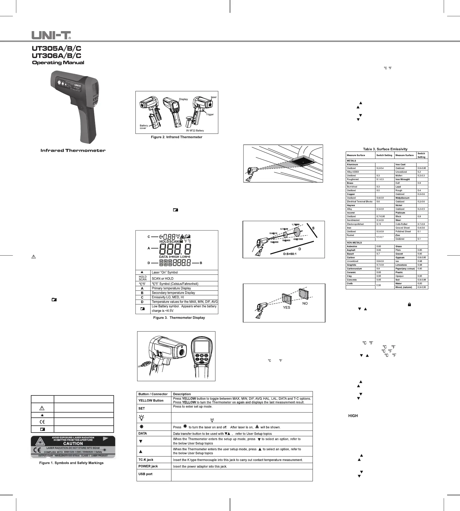
Introduction
The Model UT305A/B/C and UT306A/B/C Infrared
Thermometers (hereafter, the “Thermometer”) can
determine the surface temperature by measuring the
amount of infrared energy radiated by the target’s
surface. They have different Distance to Spot(D:S)
ratios and different temperature ranges, read the
manual for details.
The Thermometer is a non-contact infrared instrument
designed with low power consumption, which can make
the measurements much faster and easier and meanwhile
save you amount of time from frequent battery replacement.
It can be powered by the battery or the source with USB
connected to.
This Manual uses UT305A as illustration.
Contacting Uni-Trend
To contact Uni-Trend. call (852) 2950 9168 or visit Uni-
Trend web site at
Safety Information
Warning
A warning identifies conditions and actions that
pose hazards to the user. To avoid electrical shock
or personal injury, follow these guidelines:
Do not point the laser toward anyone's eye or
allow the laser to strike the eye from a reflective
surface.
Before using the Thermometer inspect the
case. Do not use the Thermometer if it appears
damaged. Look for cracks or missing plastic.
Replace the battery as soon as the battery
indicator
appears.
Do not use the Thermometer if it operates
abnormally. Protection may be impaired. When
in doubt, have the Thermometer serviced.
Do not operate the Thermometer around
explosive gas, vapor, or dust.
To avoid a burn hazard, remember that highly
reflective objects will often result in lower than
actual temperature measurements.
Do not use in a manner not specified by this
manual or the protection supplied by the
equipment may be impaired.
To avoid damaging the thermometer or the
equipment under test protect them from
EMF (electro-magnetic fields) from arc welders,
induction heaters, etc; static electricity; thermal
shock (caused by large or abrupt ambient
temperature changes – all 30 minutes from the
Thermometer to stabilize before use); placed on
or near objects of high temperature.
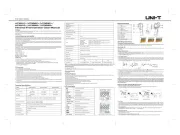
Table 1 and Figure 1 show various symbols and safety
markings that are on the Thermometer and in this
manual.
Table 1. Symbols
Symbol Explanation
Risk of danger. Important information.
See Manual.
Warning. Laser
Conforms to Standards of European
Union
Battery
Features
The Thermometer includes:
Single Laser Pointer
USB-Powered
Level 2 White Backlight (With USB connected, this
feature will be on automatically).
Current Temperature Plus MIN, MAX, DIF, AVG
Display Functions
Adjustable Emissivity
Trigger Locked
℃/℉Selectable
Tripod mount
One 9V Battery
Display
The primary temperature display reports the current or
last IR temperature reading until the 8-second hold
time elapses.
The secondary temperature display reports a choice of
maximum, minimum, difference between maximum and
minimum temperature or average value.
You can toggle through the maximum, minimum,
difference and average IR temperatures anytime the
display is on by pressing the yellow button. The MAX,
MIN, DIF and AV temperatures are constantly calculated
and updated when the trigger is pressed. After the
trigger is released, the MAX, MIN, DIF and AV
temperatures are held until the Thermometer is auto
power off.
Notes
When the battery is low
, appears on the display.
The last selection (MAX/MIN/DIF/AVG) is maintained
on the secondary display even after the Thermometer
has been turned off, providing the batteries have not
failed.
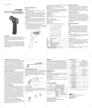
Buttons and Connector
Figure 4. Buttons and Connector
How the Thermometer Works
Infrared thermometers measure the surface temperature
of an opaque object. The Thermometer’s optics sense
infrared energy, which is collected and focused onto a
detector. The Thermometer’s electronics then translate
the information into a displayed temperature reading
which appears on the display. The laser is used for
aiming purposes only.
Operating the Thermometer
The Thermometer turns on when you press the trigger.
The Thermometer turns off when no activity is detected
for 8 seconds.
To measure temperature, aim the Thermometer at the
target, pull and hold the trigger. Release the trigger to
hold a temperature reading.
Be sure to consider distance-to-spot size ratio and filed
of view. The laser is used for aiming only.
Locating a Hot or Cold Spot
To find a hot or cold spot, aim the Thermometer outside
the target area. Then, slowly scan across the area with
an up and down motion until you located the hot or cold
spot. See Figure 5.
Figure 5. Locating Hot or Cold Spot
Distance and Spot Size
As the distance (D) from the target being measured
increases, the spot size (S) of the area measured by
the unit becomes larger. The spot size indicates 90%
encircled energy. The maximum D:S is obtained when
the Thermometer is 1000mm (100in) from the target
resulting in a spot size of 20mm (2 in). See Figure 6.
Figure 6. Distance and Spot Size
Field of View
Make sure that the target is larger than the spot size.
The smaller the target, the closer you should be to it.
See Figure 7.
Figure 7. Field of View
Emissivity
Emissivity describes the energy-emitting characteristics
of materials. Most organic materials and painted or
oxidized surfaces have an emissivity of about 0.95.
If possible, to compensate for inaccurate readings that
may result from measuring shiny metal surfaces, cover
the surface to be measured with masking tape or flat
black paint (<150 / 302 ) and use the high emissivity
setting. Allow time for the tape or paint to reach the
same temperatures as the surface beneath it. Measure
the temperature of the tape or painted surface.
emissivity selector. Even with emissivity selector, it can
be difficult to get a completely accurate infrared
measurement of a target with a shiny or metallic surface.
User Setup
Press SET button to step through Emissivity Setup→
Trigger Lock→Switching → Normal Measurement.
/
Press YELLOW button to save and exit Setup.
Emissivity Setup
This feature is to change the value of emissivity.
To adjust values for emissivity, follow the below
procedure:
1. Press SET to select emissivity set up, icon E=0 on
the display is blinking.
2. Press
to increase the value by 0.01 or press and
hold to access quick setting. The maximum value
is 1.00.
3. Press
to decrease the value by 0.01 or press and
hold to access quick setting. The minimum value
is 0.10.
The Thermometer allows you to adjust the unit’s
emissivity for the type of surface before measured.
Refer to Table 2. But it is only a typical case. You could
base on your own case and materials to have different
setting.
Trigger Lock Setup.
This feature is to set trigger lock or unlock
To lock or unlock the trigger, follow the below procedures:
1. Press SET to select trigger lock setting, the
is blinking.
2. Press
or to select ON or OFF.
When the trigger is locked, the Thermometer is on for
continuous measurement, there is no need to pull the
trigger.
When the trigger is unlocked, user needs to pull the
trigger for measurement. When you release the trigger,
the Thermometer will keep hold the measurement result
automatically.
Switching /
This feature is to select or .
1. Press SET to choose
/
selection mode,
2. Press
or to select or .
If you cannot use paint or use tape, then you could
improve the accuracy of your measurements with the
LAL Setup
This feature is to set up the low limit. When carrying
out measuring, the Thermometer beeps continuous if
the temperature is below this limit.
1. Press YELLOW button to toggle to LAL mode.
2. Press
to increase the value by 0.1 or press and
hold
to access quick setting until the maximum
value is reached or higher than HAL value. The
thermometer stops and beeps.
3. Press
to decrease the value by 0.1 or press and
hold
to access quick setting until the minimum
value is reached. The thermometer stops and beeps.
Refer refer to the below User Setup topics for details.
Backlight button. To step through Backlight Level one, Level Two and Backlight Off status,
accompanied by on/off icon.
for details.
for details.
for details.
Connect USB cable for supply power to the unit or data transmission with the software;
Backlight will automatically turn on;