Rev05 18-04-2019
Victron Energy B.V. / De Paal 35 / 1351 JG ALMERE / The Netherlands
Phone: (+31) (0)36 535 97 00 / www.victronenergy.com / e-mail: sales@victronenergy.com
Smart BatteryProtect 12/24V
ENGLISH
Installation
1. The Smart BatteryProtect (SBP) must be installed in a well-ventilated area and preferably close (max 50 cm) to the
battery (but, due to possible corrosive gasses not above the battery!). Voltage drop over a long or undersized cable
between the battery plus and the SBP may result in a short circuit alarm when starting-up the load, or unexpected
shutdown.
2. A properly sized fuse must be inserted according to local regulations in the cable between the battery and the SBP.
3. Use a 1,5mm² wire (included) for the minus connection, which should be connected directly to the battery minus (or
the chassis of a vehicle). No other equipment should be connected to this wire.
4. The SBP automatically detects the system voltage one time only after connection of plus and minus to the battery. The
selected voltage (12 or 24V) is stored, and further automatic detection is disabled. See in the programming table for
how to reset it when re-using the SBP in a different installation or use Bluetooth.
5. Do not connect the load output until the SBP has been fully programmed.
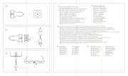
6. A remote on-off switch can be connected between Remote H and Remote L (see figure 1).
Alternatively, terminal H can be switched to battery plus, or terminal L can be switched to battery minus.
7. A buzzer, LED or relay can be connected between the alarm output and the battery plus (see figure 1). Maximum load
on the alarm output: 50 mA (short circuit proof).
Load disconnect events and alarm output options
Buzzer or LED mode (buzzer or LED connected to the alarm output):
• In case of under voltage, a continuous alarm will start after 12 seconds. The SBP will disconnect the load after 90
seconds and the alarm will stop. Reconnect delay: 30 seconds.
• In case of over voltage, the load will be disconnected immediately and an intermittent alarm will remain on until
the overvoltage problem has been corrected. There is no reconnect delay.
Relay mode (relay connected to the alarm output):
• In case of under voltage, the relay will engage after 12 seconds. The SBP will disconnect the load after 90 seconds
and the relay will disengage.
• In case of over voltage, the load will be disconnected immediately and the alarm output will remain inactive.
Overvoltage trip levels: 16V respectively 32V
Li-ion mode:
• Connect the load disconnect output of the VE.Bus BMS to Remote H terminal.
The load is disconnected immediately when the load-disconnect output of the VE.Bus BMS switches from ‘high’ to
‘free floating’ (due to battery cell under voltage, over voltage or over temperature). The under voltage thresholds
and alarm output of the SBP are inactive in this mode.
Operation
There are 6 possible error modes, indicated by the 7 segment display and on a Bluetooth enabled device:
• 1 Short circuit detected
• Over load or over temperature / P2 over temperature warning
• Under voltage / P3 under voltage warning
• Over voltage
• 5 Settings Failure
• 6 Reference Voltage Failure
• 7 BMS Lockout
After 5 minutes the error is no longer displayed to reduce current consumption.
The decimal point of the 7 segment display is used for status indication:
• On solid: the SBP attempts to activate the output
• Flash every 5s: output is active
• Flashing every 2s in Li-ion mode: output ‘connecting’
Remote control and short circuit
• The SBP will connect the load 1 second after closing the remote contact.
• The SBP will disconnect the load immediately when the remote contact is opened.
• When in Li-ion mode the SBP will observe a dead period of 30 seconds after the remote input of the SBP has
become free floating. See the note under figure 4 for a detailed description.
• In case of a short circuit, the SBP will attempt to connect the load every 5 seconds. After two attempts the display
will show (short circuit detected).
Programming
When switched off (remote open), the SBP can be programmed by connecting the PROG pin to ground. Alternatively, it
can be programmed with a Bluetooth enabled smartphone or tablet regardless of the remote status.
The 7-segment display will first step through the shutdown and restart voltages. Disconnect the PROG pin when the
desired voltage is displayed.
The display will confirm the chosen voltage and default mode () twice.
Reconnect the PROG pin to ground if another mode ( , or ) is required. Disconnect when the required mode is
displayed.
The display will confirm the chosen voltage and mode twice.
Bluetooth can be disabled/re-enabled with The Victron Connect app or by connecting the PROG pin to ground and
selecting (enable) or (disable). See table below
Programming table
Under voltage shut down
12V / 24V system
Under voltage restart
12V / 24V system
User defined settings with Bluetooth
Specifications
Maximum cont. load current
Current consumption
When on: 1,4 mA When off or low voltage shutdown : 0,9 mA
When on: 1,2 mA When off or low voltage shutdown : 0,7 mA
Max. load on alarm output
50mA (short circuit proof)
(immediate if triggered by the VE.Bus BMS)
Disengage: 10,5V or 21V Engage: 12V or 24V
Operating temperature range
Full load: -40°C to +40°C
(up to 60% of nominal load at 50°C)
0,2kg 0.5 lbs 0,5kg 0.6 lbs 0,8kg 1.8 lbs
Dimensions (hxwxd)
40 x 48 x 106 mm
1.6 x 1.9 x 4.2 inch
59 x 42 x 115 mm
2.4 x 1.7 x 4.6 inch
62 x 123 x 120 mm
2.5 x 4.9 x 4.8 inch
Smart BatteryProtect 12/24V
NEDERLANDS
Installatie
1. De Smart BatteryProtect (SBP) moet worden geïnstalleerd in een goed geventileerd gebied en bij voorkeur dicht (max. 50 cm) bij de
accu (maar in verband met de mogelijke corrosieve gassen niet boven de accu). Een spanningsverlies over een lange of te klein
bemeten kabel tussen de pluspool van de accu en de SBP kan leiden tot een kortsluiting alarmsignaal bij het opstarten of een
onverwachte uitschakeling van de SBP.
2. Een voldoende groot bemeten zekering moet conform de plaatselijke voorschriften worden geplaatst in de kabel tussen de accu en
de SBP.
3. Gebruik een 1,5mm² draad (inbegrepen) voor de minaansluiting, dat direct moet worden aangesloten op de minpool van de accu
(of het chassis van een voertuig). Geen enkele andere apparatuur mag worden aangesloten op deze draad.
4. De SBP detecteert automatisch de systeemspanning één keer na aansluiting van de plus en min op de accu. De geselecteerde
spanning (12 of 24V) wordt opgeslagen en verdere automatische detectie is uitgeschakeld. Zie in de programmeertabel voor het
resetten en het opnieuw gebruiken van de SBP in een andere installatie of gebruik Bluetooth
5. Sluit de belastingsuitgang pas aan als SBP volledig is geprogrammeerd.
6. Een externe aan-/uitschakelaar kan worden verbonden tussen de Afstandsbediening H en Afstandsbediening L (zie afb. 1).
Als alternatief, kan klem H worden overgeschakeld naar de accu pluspool, of kan klem L worden overgeschakeld naar de minpool van
de accu.
7. Een zoemer, LED of relais kan worden aangesloten tussen de alarmuitgang en de plus van de accu (zie afbeelding 1). Maximale
belasting op de alarmuitgang: 50mA (bestand tegen kortsluiting).
Belastingsontkoppelingsgebeurtenissen en alarmuitgangsopties
Zoemer- of LED modus (zoemer of LED aangesloten op de alarmuitgang):
• In geval van onderspanning wordt na 12 seconden een continu alarm afgegeven. De SBP zal de belasting na 90s afschakelen en
het alarm wordt gestopt. Inschakelvertraging: 30s.
• In geval van overspanning wordt de belasting direct ontkoppeld en wordt het alarm intermitterend afgegeven tot het
overspanningsprobleem is verholpen. Er is geen herverbindingsvertraging.
Relaismodus (relais aangesloten op de alarmuitgang):
• In geval van onderspanning wordt het relais na 12 seconden geactiveerd. De SBP zal de belasting na 90 seconden ontkoppelen
en het relais wordt gedeactiveerd.
• In geval van overspanning wordt de belasting direct ontkoppeld en blijft het alarm inactief. Overspanning drempel niveaus:
16V respectievelijk 32V
Li-ionmodus:
• Verbind de laad-ontkoppeluitgang van de VE.Bus BMS naar de Afstandsbediening H klem.
De belasting wordt direct ontkoppeld als de belasting ontkoppelingsuitgang van het VE.Bus BMS van ‘hoog’ naar ‘free floating’
overschakelt (door onderspanning, overspanning of overtemperatuur van de accucel). De onderspanningsdrempel en
alarmuitgang van de SBP zijn in deze modus inactief.
Bediening
Er zijn 6 mogelijke foutmodi, aangeduid door de 7 segmentweergave en op een Bluetooth geactiveerd apparaat:
• 1 Kortsluiting gedetecteerd
• Overbelasting of overtemperatuur / P2 waarschuwing te hoge temperatuur
• Onderspanning / P3 onderspanning waarschuwing
• Overspanning
• 5 Fout bij de Instellingen
• 6 Referentie Spanningsfout
• 7 BMS uitsluiting
Na 5 minuten wordt de storing niet meer weergegeven om het stroomverbruik te verminderen.
De decimale punt van het uit 7 segmenten bestaande display wordt gebruikt voor de statusindicatie:
• Brandt continu: de SBP probeert om de uitgang te activeren
• Knippert om de 5 sec: de uitgang is actief
• Knippert om de 2 sec in li-ionmodus: uitgang ‘wordt verbonden’
Afstandsbesturing en kortsluiting
• De SBP verbindt de belasting 1 seconde na het sluiten van het contact voor in-/uitschakelen op afstand.
• De SBP zal de belasting direct ontkoppelen als het contact voor in-/uitschakelen op afstand wordt geopend.
• Wanneer in de Li-ion-modus de SBP een dode periode van 30 seconden zal waarnemen nadat de externe invoer van de SBP vrij
zwevend is geworden. Zie de opmerking bij afbeelding 4 voor een gedetailleerde beschrijving.
• In geval van kortsluiting zal de SBP proberen om de belasting om de 5 seconden te koppelen. Na twee pogingen zal op het
display (kortsluiting gedetecteerd) worden weergegeven.
Programmeren
Wanneer uitgeschakeld (afstandsbediening open), kan de SBP worden geprogrammeerd door de PROG-pin te aarden. Als
alternatief, kan het worden geprogrammeerd met een smartphone waarvan Bluetooth is geactiveerd of tablet ongeacht
de afstand.
De 7-segmentweergave zal eerst het uitschakelen en de herstartspanningen weergeven. De PROG-pin ontkoppelden
wanneer de gewenste spanning wordt weergegeven.
Het display zal de gekozen spanning en de standaardmodus () twee keer bevestigen.
Verbind de pin PROG weer met de aarde als een andere modus ( of ) is gewenst. Koppel de pin weer los als de
gewenste modus wordt weergegeven.
Het display zal de gekozen spanning en modus twee keer bevestigen.
Bluetooth kan worden in-/uitgeschakeld met de Victron Connect app of door het verbinden van de PROG-pin op de
aarding en selecteren van (inschakelen) of (uitschakelen). Zie de onderstaande tabel
Programmeringstabel
Onderspanningsuitschakeling
12V- / 24V-systeem
Onderspanningsherstart
12V- / 24V-systeem
Door de gebruiker gedefinieerde instellingen met Bluetooth
Systeemspanning detecteren
Specificaties
Max. continue belastingsstroom 65A 100A 220A
Bedrijfsspanningsbereik 6 – 35V
Stroomverbruik
Wanneer ingeschakeld: 1,4mA Wanneer uitgeschakeld of lage spanning uitschakeling: 0,9mA
Wanneer ingeschakeld: 1,2mA Wanneer uitgeschakeld of lage spanning uitschakeling: 0,7mA
Alarmuitgangsvertraging 12 seconden
Max. belasting op alarmuitgang 50 mA (bestand tegen kortsluiting)
Afschakel vertraging 90 seconden (direct als geactiveerd door VE.Bus BMS)
Herverbinding vertraging 30 seconden
Standaarddrempels Ontkoppelen: 10,5V of 21V Koppelen: 12V of 24V
Bedrijfstemperatuurbereik Volledige belasting: -40°C tot +40°C (tot 60% van de nominale belasting bij 50°C)
Gewicht 0,2kg 0,5 kg 0,8kg