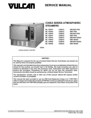
Vulcan C24ET6-PS Manual

Vulcan Damprenser C24ET6-PS

Læs gratis den danske manual til Vulcan C24ET6-PS (68 sider) i kategorien Damprenser. Denne vejledning er vurderet som hjælpsom af 30 personer og har en gennemsnitlig bedømmelse på 4.8 stjerner ud af 15.5 anmeldelser. Har du et spørgsmål om Vulcan C24ET6-PS, eller vil du spørge andre brugere om produktet?

Side 1/68
C24ET-SERIES STEAMERS
ML-152035 C24ET6 - LWE1
ML-152036 C24ET6 - LWE2
ML-152037 C24ET10 - LWE1
ML-152038 C24ET10 - LWE2
ML-152039 C24ET6 - 1
ML-152040 C24ET6 - 2
ML-152041 C24ET10 - 1
ML-152042 C24ET10 - 2
ML-152043 C24ET6 - 21
ML-152044 C24ET6 - 22
ML-152045 C24ET10 - 21
ML-152046 C24ET10 - 22
- NOTICE -
This Manual is prepared for the use of trained Hobart Service Technicians and should not
be used by those not properly qualified.
This manual is not intended to be all encompassing. If you have not attended a Hobart Service
School for this product, you should read, in its entirety, the repair procedure you wish to
perform to determine if you have the necessary tools, instruments and skills required to
perform the procedure. Procedures for which you do not have the necessary tools,
instruments and skills should be performed by a trained Hobart Service Technician.
The reproduction, transfer, sale or other use of this manual, without the express written
consent of Hobart, is prohibited.
This manual has been provided to you by ITW Food Equipment Group LLC ("ITW FEG")
without charge and remains the property of ITW FEG, and by accepting this manual you agree
that you will return it to ITW FEG promptly upon its request for such return at any time in the
future.
SERVICE MANUAL
A product of Vulcan-Hart 3600 North Point Blvd Baltimore, MD 21222
F45636 Rev. A (0821)
TABLE OF CONTENTS
SERVICE UPDATES ....................................................................................... 4
SERVICE UPDATES ................................................................................... 4
TIS DOCUMENT LIST - C24ET SERIES STEAMERS . . . . . . . . . . . . . . . . . . . . . . . . . . . . . . . . . . . . . . . . . . . . . . . . . . . 4
GENERAL .................................................................................................. 6
INTRODUCTION . . . . . . . . . . . . . . . . . . . . . . . . . . . . . . . . . . . . . . . . . . . . . . . . . . . . . . . . . . . . . . . . . . . . . . . . . . . . . . . . . . . . . . . 6
OPERATION . . . . . . . . . . . . . . . . . . . . . . . . . . . . . . . . . . . . . . . . . . . . . . . . . . . . . . . . . . . . . . . . . . . . . . . . . . . . . . . . . . . . . . . . . . . 6
INSTALLATION ........................................................................................ 6
LUBRICATION ......................................................................................... 6
CLEANING ............................................................................................. 6
ELECTRICAL SPECIFICATIONS - BASIC / PROFESSIONAL MODELS . . . . . . . . . . . . . . . . . . . . . . . . . . . . . . . . . . 7
ELECTRICAL SPECIFICATIONS - LWE MODEL . . . . . . . . . . . . . . . . . . . . . . . . . . . . . . . . . . . . . . . . . . . . . . . . . . . . . . . . 7
WATER SPECIFICATIONS - ALL MODELS ............................................................. 7
TOOLS ................................................................................................. 8
REMOVAL AND REPLACEMENT OF PARTS . . . . . . . . . . . . . . . . . . . . . . . . . . . . . . . . . . . . . . . . . . . . . . . . . . . . . . . . . . . . . . 10
RIGHT SIDE TOP PANEL . . . . . . . . . . . . . . . . . . . . . . . . . . . . . . . . . . . . . . . . . . . . . . . . . . . . . . . . . . . . . . . . . . . . . . . . . . . . . 10
RIGHT SIDE BOTTOM PANEL ........................................................................ 10
LEFT SIDE TOP PANEL ............................................................................... 10
LEFT SIDE BOTTOM PANEL .......................................................................... 11
TOP REAR PANEL .................................................................................... 11
BOTTOM REAR PANEL . . . . . . . . . . . . . . . . . . . . . . . . . . . . . . . . . . . . . . . . . . . . . . . . . . . . . . . . . . . . . . . . . . . . . . . . . . . . . . . 12
BOTTOM FRONT PANEL . . . . . . . . . . . . . . . . . . . . . . . . . . . . . . . . . . . . . . . . . . . . . . . . . . . . . . . . . . . . . . . . . . . . . . . . . . . . . 13
TOP COVER .......................................................................................... 13
DOOR ................................................................................................ 13
DOOR GASKET ....................................................................................... 14
DOOR HANDLE ....................................................................................... 14
DOOR LATCH ........................................................................................ 15
HINGE BEARINGS . . . . . . . . . . . . . . . . . . . . . . . . . . . . . . . . . . . . . . . . . . . . . . . . . . . . . . . . . . . . . . . . . . . . . . . . . . . . . . . . . . . . 16
DRAIN BOX . . . . . . . . . . . . . . . . . . . . . . . . . . . . . . . . . . . . . . . . . . . . . . . . . . . . . . . . . . . . . . . . . . . . . . . . . . . . . . . . . . . . . . . . . . . 16
CONDENSATE THERMOSTAT . . . . . . . . . . . . . . . . . . . . . . . . . . . . . . . . . . . . . . . . . . . . . . . . . . . . . . . . . . . . . . . . . . . . . . . . 17
HEATING ELEMENT . . . . . . . . . . . . . . . . . . . . . . . . . . . . . . . . . . . . . . . . . . . . . . . . . . . . . . . . . . . . . . . . . . . . . . . . . . . . . . . . . . 18
STEAM GENERATOR TANK . . . . . . . . . . . . . . . . . . . . . . . . . . . . . . . . . . . . . . . . . . . . . . . . . . . . . . . . . . . . . . . . . . . . . . . . . . 19
MOTORIZED DRAIN VALVE (PROFESSIONAL) . . . . . . . . . . . . . . . . . . . . . . . . . . . . . . . . . . . . . . . . . . . . . . . . . . . . . . . 21
DRAIN TANK MANUALLY . . . . . . . . . . . . . . . . . . . . . . . . . . . . . . . . . . . . . . . . . . . . . . . . . . . . . . . . . . . . . . . . . . . . . . . . . 21
REMOVAL . . . . . . . . . . . . . . . . . . . . . . . . . . . . . . . . . . . . . . . . . . . . . . . . . . . . . . . . . . . . . . . . . . . . . . . . . . . . . . . . . . . . . . . . 23
SUPER-HEATER ELEMENT .......................................................................... 24
HOLD THERMOSTAT ................................................................................. 24
HIGH LIMIT THERMOSTAT ........................................................................... 25
WATER LEVEL PROBES .............................................................................. 25
SENSOR PROBE ..................................................................................... 26
UPPER COOKING COMPARTMENT . . . . . . . . . . . . . . . . . . . . . . . . . . . . . . . . . . . . . . . . . . . . . . . . . . . . . . . . . . . . . . . . . . 26
LOWER COOKING COMPARTMENT . . . . . . . . . . . . . . . . . . . . . . . . . . . . . . . . . . . . . . . . . . . . . . . . . . . . . . . . . . . . . . . . . . 27
PRESSURE SWITCH . . . . . . . . . . . . . . . . . . . . . . . . . . . . . . . . . . . . . . . . . . . . . . . . . . . . . . . . . . . . . . . . . . . . . . . . . . . . . . . . . 29
VACUUM RELIEF VALVE ............................................................................. 30
FILL VALVES ......................................................................................... 30
ELECTRONIC COMPONENT .......................................................................... 31
PID CONTROLLER . . . . . . . . . . . . . . . . . . . . . . . . . . . . . . . . . . . . . . . . . . . . . . . . . . . . . . . . . . . . . . . . . . . . . . . . . . . . . . . . . . . 31
SOLID STATE CONTACTOR .......................................................................... 32
ON/OFF SWITCH . . . . . . . . . . . . . . . . . . . . . . . . . . . . . . . . . . . . . . . . . . . . . . . . . . . . . . . . . . . . . . . . . . . . . . . . . . . . . . . . . . . . . 32
INDICATOR LIGHT ASSEMBLY ....................................................................... 32
DOOR SWITCH . . . . . . . . . . . . . . . . . . . . . . . . . . . . . . . . . . . . . . . . . . . . . . . . . . . . . . . . . . . . . . . . . . . . . . . . . . . . . . . . . . . . . . . 33
TIMER . . . . . . . . . . . . . . . . . . . . . . . . . . . . . . . . . . . . . . . . . . . . . . . . . . . . . . . . . . . . . . . . . . . . . . . . . . . . . . . . . . . . . . . . . . . . . . . . 33
BUZZER .............................................................................................. 34
SERVICE PROCEDURES AND ADJUSTMENTS . . . . . . . . . . . . . . . . . . . . . . . . . . . . . . . . . . . . . . . . . . . . . . . . . . . . . . . . . . . 35
DOOR LATCH ADJUSTMENT . . . . . . . . . . . . . . . . . . . . . . . . . . . . . . . . . . . . . . . . . . . . . . . . . . . . . . . . . . . . . . . . . . . . . . . . . 35
C24ET-SERIES STEAMERS
F45636 Rev. A (0821) Page 2 of 68


Produkt Specifikationer

Mærke: Vulcan
Kategori: Damprenser
Model: C24ET6-PS

Har du brug for hjælp?

Hvis du har brug for hjælp til Vulcan C24ET6-PS stil et spørgsmål nedenfor, og andre brugere vil svare dig