First, please carefully read the “IMPORTANT SAFETY INSTRUCTIONS” in the “Technical Specifications.”
Thank you for your purchase of the Yamaha MA2030a/PA2030a power amplifier. This power amplifier was
designed for background music and public address applications in places such as stores, commercial
spaces, and so on. This manual contains installation and setting up information for installers, and
operation instructions for users. Please read through this manual carefully before beginning use, so that
you will be able to take full advantage of the device’s various functions. After you have read the manual,
• The illustrations as shown in this manual are for instructional purposes only.
• The company names and product names in this manual are the trademarks or registered trademarks of
their respective companies.
• Software may be revised and updated without prior notice.
mark indicates content that is unique to the MA2030a, and indicates
content unique to the PA2030a. Contents that are common to both have no marks.
• Amplifier illustrations are mainly from the MA2030a. Where necessary, illustrations of the PA2030a are
• Supports both kinds of speaker connection: high-impedance connection and low-impedance
• Equipped with digital processor (Feedback Suppressor, Ducker, Leveler).
• Optional PA2030a expansion amplifier enables connection of additional speakers.
• Euroblock plugs (3-pin, 3.50mm pitch) x 1 , x 2
• echnical Specifications: includes block diagram, dimensions, and input/outputT
• Owner’s Manual (this sheet)
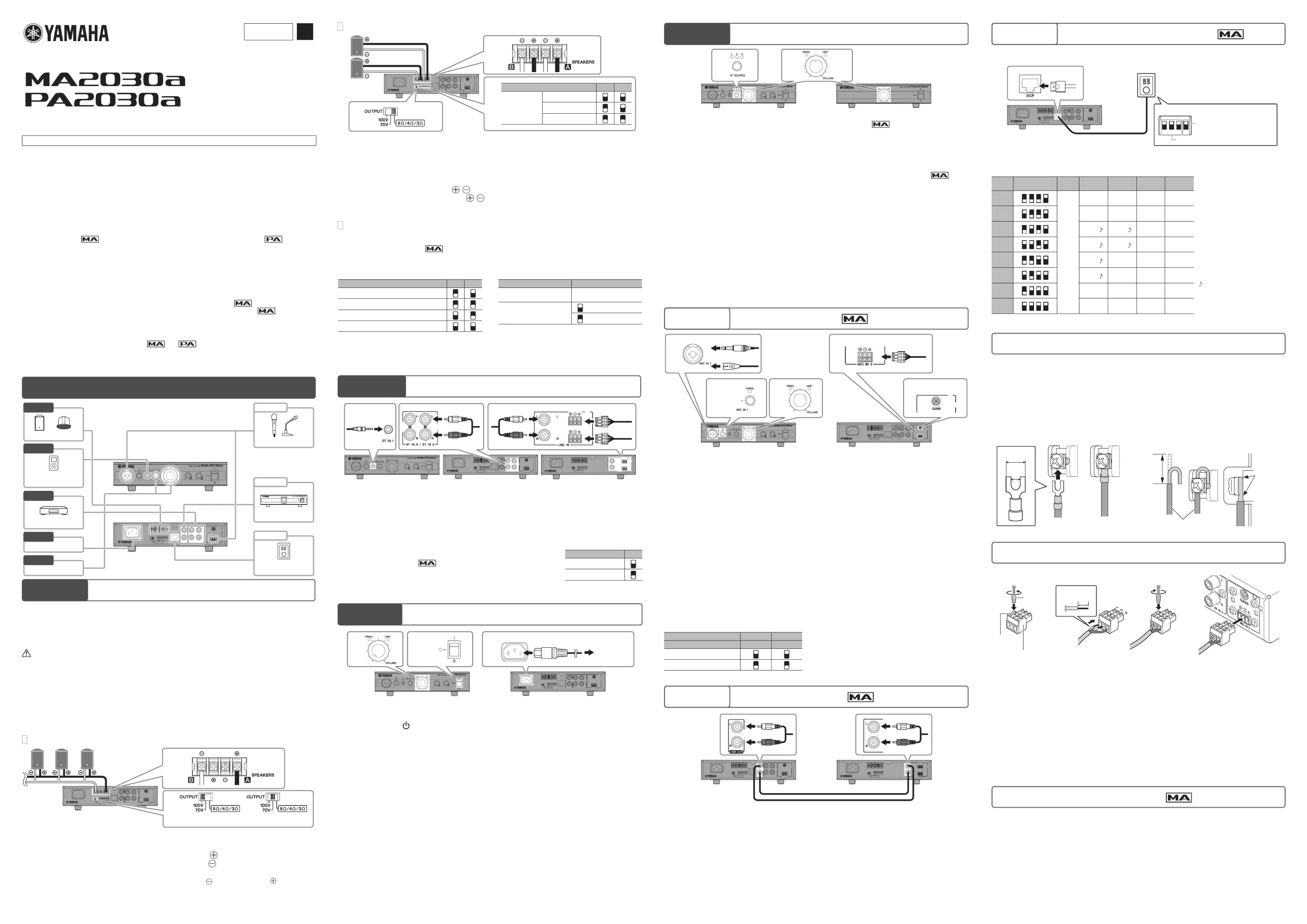
Change the setting depending on the speaker connection (high- or low-impedance connection), the kind
of speakers, and the installation location of the speakers. Refer to “Connecting Speaker Cables” at the
right bottom on this page and the explanation of high-impedance connection, etc. at the following URL.
Yamaha Pro Audio site: “Better Sound for Commercial Installations”:
http://www.yamahaproaudio.com/global/en/training_support/better_sound/
• Before connecting speakers, make sure that the power of the device is turned off. If the power is on, there is a risk of
• Match the impedance settings of this device and the connected speakers. Use in which the impedance does not
match may cause damage to the device or speakers.
• Ensure that load is not applied to the speaker cable.
• In a high-impedance installation, make sure that the sum of the power input ratings of the speakers to be connected
• In a low-impedance installation, make sure that the total impedance of speakers to be connected is at least 3 ohms.
• Connectable cable gauges: AWG20 (0.5mm
High-impedance Connections (60W x 1 channel)
Set the speaker output to high-impedance by setting the [OUTPUT] switch to
[100V] or [70V] corresponding to the maximum output voltage.
Use speaker cables to connect the [SPEAKERS A] terminal to the positive “+”
terminals of the speakers, and the [SPEAKERS B] terminal to the negative “-”
In case of high-impedance connection, the [SPEAKERS A] and [SPEAKERS B] terminals are
not used. Do not connect to the terminals.
In high-impedance settings, the speaker output is processed through a high pass filter (80Hz, 18dB/oct.).
Low-impedance Connections (30W x 2 channels)
Set the speaker output to low-impedance connection by setting the [OUTPUT] switch
Set the [SETUP] DIP switch 1/2 corresponding to the specications of the speakers to
Connect the [SPEAKERS A] / terminals to the “+”/“-” terminals of the rst
speaker, and the [SPEAKERS B]
/ terminals to the “+”/“-” terminals of the second
Configuration of Speaker Output Signal
Connecting Yamaha Speakers
Setting the [SETUP] DIP switches optimizes the
output signal to match Yamaha VXS/VXC speakers
designed for commercial installations.
Yamaha VXS series (surface mount-type)
Yamaha VXC series (ceiling-type)
For information on the speaker output settings of the
PA2030a, refer to “Controls and functions.”
Setting mono/stereo output
In a low-impedance installation, if speakers are
placed in a stereo arrangement, set to stereo
—: Setting is not required. (Either up or down can be used.)
*1: When stereo audio is output, the left channel signal
is output from the [SPEAKERS A] terminals and the
right channel signal is output from the [SPEAKERS B]
Connecting External Devices
RCA type RCA type Euroblock
MA2030a rear panel PA2030a rear panel
Connect a BGM (background music) tuner, a CD player, a portable audio player, etc. to the stereo input jacks
Refer to “Attaching Euroblock Plugs” for Euroblock plug installation.
Make sure that this device and all devices to be connected are turned off.
Connect this device and any external devices with appropriate cables.
Leveler (suppressing wide playback volume variations)
The Leveler function automatically suppresses and corrects for large changes in
the playback volume from external devices for a more consistent sound, such as
when reproducing BGM (background music).
Connecting Power Cord and Turning On
MA2030a front panel MA2030a rear panel
Make sure power switches of this device and devices connected to this device are
turned off (in position).
Turn the [VOLUME] knob all the way to the left.
Connect the supplied power cord to the AC IN connector.
Insert the power cord plug into an appropriate outlet.
After turning on the connected devices (portable audio players, CD players, etc.), turn
Note • Before turning on the power, please check that there are no problems with the cabling, connections, and so on.
• When turning the system off, turn off this device, and then connected devices.
MA2030a front panel PA2030a front panel
Select a stereo input by rotating the [ST SOURCE] knob.
The [ST SOURCE] indicator corresponding to the selected input signal lights.
Input audio signal from the external device, and rotate the [VOLUME] knob.
Make sure that the [VOLUME SIGNAL] indicator lights according to the sound input and that sound
Matching the volume levels of external devices (including microphones)
When connecting two or more external devices, you can lower the volume of the louder devices (or
microphones) to match the level of the faintest device. If you are using microphones, follow the instructions
in “Option 1 Using Microphones” to adjust the volume level of microphones before executing the operation
Select the stereo input with the loudest sound by rotating the [ST SOURCE] knob.
Press and hold the [ST SOURCE] knob until the [ST SOURCE] indicator ashes.
Rotate the [ST SOURCE] knob to the left until the volume decreases to the point that
lowers as loud as that of the faintest sounding stereo input (or microphones).
As the volume becomes fainter, the flashing rate of the [ST SOURCE] indicator becomes slower.
Push the [ST SOURCE] knob to complete the adjustment.
The [ST SOURCE] indicator lights.
Adjustable range: -18dB – 0dB, -9dB as the default setting
Turn the [MIC IN 1] knob or the [MIC IN 2 GAIN] trimmer all the way to the left, and
connect a microphone to the [MIC IN 1] jack or the [MIC IN 2] connector.
Set the [VOLUME] knob to roughly a 2:00 position.
Loudly speak into the microphone, and turn the [MIC IN 1] knob or the [MIC IN 2 GAIN]
trimmer to the right until the output signal is not distorted.
If you input a loud voice but the output is small, raise the volume with the [VOLUME] knob.
If the sound out of the speakers is too loud, lower the volume with the [MIC IN 1] knob or the [MIC IN 2
Make sure the input from external devices matches the volume levels of the
microphones and the external devices.
Refer to “Matching the volume levels of external devices (including microphones)” in “Step 4 Adjusting
Volume” for instructions.
• To adjust the [MIC IN 2 GAIN] trimmer, use a slotted screw driver.
• Refer to “Attaching Euroblock Plugs” for installation of Euroblock plugs.
• The input signal is always processed through a high pass filter (120Hz, 12dB/oct.) to cut off low frequency signals
as well as a Feedback Suppressor to suppress howling.
Ducker (lowering the volume of the other channels automatically when a
microphone signal is input)
Jack/connector [MIC IN 1] [MIC IN 2]
Note • If both Duckers of the [MIC IN 1] jack and the [MIC
IN 2] jack are enabled, the Ducker for the [MIC IN
• Activating the Ducker lowers the output volume of
the stereo inputs by 24dB and mutes that of the
Connecting the MA2030a and PA2030a lets you increase the number of driven speakers. Connect the [LINE
OUT] jacks of MA2030a and the [LINE IN] jacks of PA2030a.
Operating with Control Panel
Connecting Yamaha Digital Control Panel DCP1V4S-US/EU to MA2030a enables you to control the
volume, to switch inputs, etc. remotely.
Yamaha Digital Control Panel
When connecting to MA2030a,
set the DIP switch 4 to ON
The functions of the knob and the switches of DCP1V4S-US/EU can be configured with DIP switches at
the back of DCP1V4S-US/EU.
Knob Switch 1 Switch 2 Switch 3 Switch 4
Volume: Adjusts the volume output
to the [SPEAKERS] terminals and
Stereo 1/2/3: Switches to stereo
Mic. 1/2: Turns on/off microphone
input 1/2. When a microphone
is on, the switch indicator of the
control panel lights and the stereo
• If the panel ID is set to 3, the
stereo input is not muted even
though the microphone is on.
• If the panel ID is set to 7, the
microphone stays on while
: A chime sounds when the
microphone is turned on/off
—: Does not work. (No function is
Stereo 1 Stereo 2 Stereo 3 Mic. 1/2
Note Refer to “DCP1V4S-US/DCP1V4S-EU Owner’s Manual” for DCP1V4S-US/EU installation.
Connecting Speaker Cables
The [SPEAKERS] output connectors on the rear panel are barrier strip type connectors. The connections
are described below for two methods: using a spade lug and using a bare conductor.
Ensure that load is not applied to the speaker cable.
Note Connect the cables so that the amplifier’s “+” and “-” symbols match those of the speaker. If they are reversed,
the phase will be reversed and the sound will not be output correctly.
Loosen the screw, insert the spade lug all the
way from below, and tighten the screw.
When using a bare conductor
Loosen the screw, wrap the conductor wire around
the barrier strip terminal, and tighten the screw. Be
sure that the bare wire does not touch the chassis.
Attaching Euroblock Plugs
Note • You must use the supplied Euroblock plugs. If the plugs have been lost, please contact your Yamaha dealer.
• Recommended cable gauges for the Euroblock plug: AWG26 (0.13mm
• To prepare the cable for attachment to a Euroblock connector, strip the wire as shown in the illustration using
stranded wire to make connections. With a Euroblock connection, stranded wires may be prone to breakage
because of metal fatigue due to the weight of the cable or due to vibration. When rack mounting your device,
use a lacing bar when possible to bundle and fasten the cables.
• Do not tin (solder) the exposed end.
Securely tighten terminal screws.
Insert the Euroblock plug into the [MIC IN 2] terminal of MA2030a or the [LINE IN]
Switching the panel lock on/off
Changes by several knobs can be locked, so that the settings of the device are not affected by accidental
touch or unauthorized operation. The [ST SOURCE], [SOURCE EQ BASS] and [SOURCE EQ TREBLE]
Adjust the [ST SOURCE], [SOURCE EQ BASS] and [SOURCE EQ TREBLE] knobs
to the desired fixed settings.
Press the [ST SOURCE] knob three times within a second.
To set the panel lock off, press the [ST SOURCE] knob three times within a second