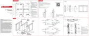
Abb./g./schéma/a./ill. 5a
Abb./g./schéma/a./ill. 5b
Abb./g./schéma/a./ill. 7Abb./g./schéma/a./ill. 6
Abb./g./schéma / a./ill. 1
Montage- und Bedienungsanleitung
Vielen Dank dass Sie sich für dieses ABUS Produkt entschieden haben!
Bitte lesen Sie diese Anleitung vor der Montage und Inbetriebnahme sorgfältig durch. Bewahren Sie die Anleitung auf und
weisen Sie jeden Nutzer auf die Bedienung des Produktes hin.
Verpackungsmaterial von Kindern fernhalten: Erstickungsgefahr!
ABUS-Tür-Zusatzschlösser geben zusätzlichen Schutz gegen unberechtigtes Eindringen in Räume, werden auf der Griseite
montiert und eignen sich für nach innen önende, einügelige Türen. Mit dieser Montage- und Bedienungsanleitung können
nicht alle Anwendungsmöglichkeiten angesprochen werden. Gegebenenfalls einen Fachhändler fragen.
Die optimale Schutzwirkung wird erreicht, wenn entsprechend dieser Montage- und Bedienungsanleitung vorgegangen wird.
Die Befestigungsschrauben sollen zur Vermeidung von Überdrehung mit einem entsprechenden Werkzeug von Hand festgezo-
gen werden. Ausschließlich ABUS-Befestigungsmaterial verwenden.
Für eventuell auretende Verletzungen bzw. Schäden, die bei der Montage und/oder durch unsachgemäße Handhabung ent-
stehen, übernimmt der Hersteller keine Haung! Dieses Produkt darf nicht im Bereich von Notausgängen eingesetzt werden.
VdS Anerkennung: Die Tür-Zusatzschlösser 7510, 7525 mit VdS Anerkennung sind unter der Nummer M 113311 VdS registriert.
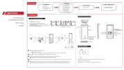
ABUS-Tür-Zusatzschlösser eignen sich für nach innen önende Falz- und Stumpüren, DIN-rechts oder DIN-links
angeschlagen (Abb.1), für Falzstärken von 0 bis 29 mm und Türstärken von 38 bis 80 mm. Bei stabilen Türen sollte die
Montageposition oberhalb des Einsteckschlosses sein (Abb. 2). Bei weniger stabilen Türen oder bei erhöhten Sicherheitsanfor-
derungen empehlt sich die Montage von 2 Türzusatzschlösser. Es wird dann eines unter- und eines oberhalb des Einsteck-
schlosses montiert (Abb. 2). Bitte darauf achten, dass eine bequeme Bedienung möglich ist. Um den Außenzylinder zusätzlich
gegen Angrie und Manipulationen zu schützen, empfehlen wir den Einsatz der ABUS Panzerplatte PZS 80.
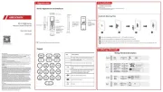
1. 1 Stück Schlosskasten 5. 1 Zylinder mit 3 Schlüsseln
2. 1 Stück Schließkasten (7530 + 7535 mit Sperrbügel) 6. 1 Schutzplatte
3. 1 Stück Anschraubleiste für Schließkasten (14 mm) 7. 1 Satz Befestigungsmaterial
4. 1 Satz Kunststounterlagen für Schließkasten (je 1 x 8, 4, 2, 1 mm)
• Kreuzschlitzschraubendreher • Lochfräse oder -säge Ø von 29 - 31 mm
• Bohrmaschine • Bohrer Ø 12 mm für Zylinderloch
• Wasserwaage, Metermaß • Diverse Metallbohrer (auch bei Holz verwendbar)
• Reißnadel oder ähnliches
• Vor der Montage bitte die Einstellung der Tür überprüfen. Es ist sicherzustellen, dass sich die Tür einwandfrei önen und
• Bitte überprüfen, ob das angegebene Mindestmaß an der Tür vorhanden ist (Abb. 3).
• Die Bohrlochtiefen bzw. die Schraubenlängen müssen auf die örtlichen Gegebenheiten abgestimmt werden.
• Austreten des Bohrers bzw. der Schrauben auf der Rückseite vermeiden. Ggf. mit Bohranschlag arbeiten oder die
vorhandenen Schrauben kürzen.
• Beim Bohren keine beweglichen Teile oder Dichtungen beschädigen.
• Schließrichtung DIN-rechts oder DIN-links ermitteln (eventuell umstellen).
Schließrichtung umstellen (bei Bedarf)
Die Schließrichtung ist für DIN-rechte Türen vormontiert. Falls die Schließrichtung für DIN-linke Türen geändert werden soll,
muss wie folgt vorgegangen werden:
1. Schraube (1) herausdrehen und Antriebselement (2) abnehmen (7510, 7530) (Abb. 5a).
2. Blattfeder (3) herausnehmen.
3. Riegelwerk (4) hinten anheben und herausziehen (7510 – 7535).
4. Riegelwerk (4) um 180° drehen und sinngemäß wieder einsetzen (7510 – 7535).
5. Blattfeder (3) auf der anderen Seite sinngemäß wieder einsetzen.
6. Antriebselement (2) aufsetzen und mit Schraube (1) festdrehen (7510, 7530) (Abb. 5b).
7. Achtung: Bei 7525 und 7535 zusätzlich die Schrauben (1) lösen, Abdeckhaube um 180° drehen und die Schrauben (1)
wieder vorsichtig festdrehen. (Abb. 4)
7530 + 7535: Sperrbügel umstellen von DIN-rechts auf DIN-links (bei Bedarf)
Der Sperrbügel ist für DIN rechte Türen vormontiert. Bei DIN linken Türen muss der Sperrbügel wie folgt umgelegt werden:
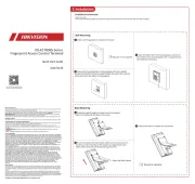
1. Sicherungsblech (1) mit Schraubendreher lösen (Abb. 6).
2. Haltebolzen (2) mit O-Ring (3) herausnehmen, Sperrbügel (4) mit Haltebolzen (2) und O-Ring (3) sinngemäß an der
gegenüber liegenden Bohrung einsetzen.
3. Sicherungsblech (1) aufstecken (Abb. 7).
Schließkasten auf dem Türrahmen
1. Bei geschlossener Tür in gewünschter Höhe an der Türkante eine Bleistilinie ziehen (Abb. 8). Tür önen, Schablone für
Schließkästen „Falztür“ an die Bleistilinie anlegen. 4 der 6 Löcher A (Abb. 9) zur optimal geeigneten Befestigung aus-
wählen, anzeichnen und vorbohren (siehe Bohrtabelle). Anschraubleiste für Schließkasten mit Kunststounterlagen
unterfüttern, bis die Anschraubleiste / das Unterlagenpaket bündig mit der Türoberäche abschließt.
2. Anschraubleiste und Unterlagen mit 4 Schrauben Ø 5,5 x 50 mm an den vorgebohrten Punkten anschrauben (Abb. 9).
Zusätzlich besteht die Möglichkeit, zur Mauerverankerung den Rahmendübel Ø 10 x 120 mm einzusetzen. Das Dübelloch B
(Abb. 10) schräg durch die Anschraubleiste des Schließkastens bohren Ø 10 mm, Dübel einsetzen und Schraube fest
3.1 Zusatzschlösser 7510, 7525
Schließblech mit den Schrauben M6 x 16 mm (selbstschneidend) auf der Anschraubleiste befestigen (Abb. 11).
3.2 Zusatzschlösser 7530, 7535
Schließblech mit Sperrbügel mit den Schrauben M6 x 16 (selbstschneidend) auf der Anschraubleiste befestigen (Abb. 12).
Schablone für „Stumpür“ (7510, 7525) in gewünschter Höhe an die Kante des Türrahmens anlegen. Löcher D (Abb. 13)
anzeichnen und vorbohren (siehe Bohrtabelle). Schließblech mit 4 Schrauben Ø 5,5 x 50 mm an den vorgebohrten Punkten
anschrauben. Zusätzlich besteht die Möglichkeit, zur Mauerverankerung einen Rahmendübel Ø 10 x 120 mm einzusetzen. Das
Dübelloch E (Abb. 13) durch das Schließblech bohren Ø 10 mm, Dübel einsetzen und Schraube fest eindrehen.
Schablone für „Stumpür“ (7530, 7535) in gewünschter Höhe an die Kante des Türrahmens anlegen. Löcher F (Abb. 14)
anzeichnen und vorbohren (siehe Bohrtabelle). Schließblech mit 3 Schrauben Ø 5,5 x 50 mm an den vorgebohrten Punkten
1. Bei geschlossener Tür den Schablonenausschnitt an die Türkante anlegen und zum Schließkasten mittig ausrichten. Die 2
Bohrungen (M), die Bohrungen Ø 12 mm (K oder H), die Bohrung Ø 6,5 mm (N) und die Bohrung Ø 29 - 31 mm, (G und H =
Türscharnier rechts, K und L = Türscharnier links) auf der Tür anzeichnen.
2. Die 2 Befestigungslöcher (M) mit Ø 3 mm vorbohren, nicht durchbohren, ggf. mit Bohranschlag arbeiten. Für die Löcher K
oder H, N und das Zylinderloch L mit einem Bohrer Ø 3 mm durch die Tür bohren. Dann die Löcher in der Reihenfolge:
1. Ø 6,5 mm (N), 2. Ø 12 mm (K oder H) und dann das Zylinderloch (L oder G) mit der Lochsäge/ - fräse Ø 29 - 31 mm von der
Innen- und Außenseite des Türblattes zur Mitte hin auohren. (Beidseitig sauberer Ausschnitt).
3. Zylinder ohne Schlüssel in Schutzplatte einsetzen und mit 2 Schrauben M5 x 20 mm befestigen (Abb. 15). Von außen in das
Zylinderloch einstecken und die Mitnehmerstange so kürzen, so dass diese 3 - 5 mm aus der Türinnenseite heraussteht
4. Riegelwerk hinten anheben und Riegel ganz nach vorne schieben (Abb. 17). Der Mitnehmersti des Schlosskastens muss
nach unten zeigen. Schlosskasten und Zylinder so zusammenführen, dass die Mitnehmerstange des Zylinders in den
Schlitz des Mitnehmereinsatzes fasst. Schlosskasten und Zylinder mit Senkkopfschrauben M6 x 27 mm (Türblätter 38 –
42 mm) verschrauben, dazu die Blattfeder (3) Abb. 5a oder 5b etwas anheben. Im Falzbereich mit 2 Schrauben
Ø 4,8 x 16 mm verschrauben. Den Riegel komplett zurückschließen.
5. Abdeckhaube des Schlosskastens aufsetzen und mit Schrauben M5 x 8 mm befestigen. Funktion des Tür-Zusatzschlosses
von innen und außen überprüfen und ggf. korrigieren. Abdeckhaube des Schließkastens aufdrücken (Abb. 11 + 14).
Von außen per Schlüssel, von innen mit Drehknopf (7510, 7530) oder Schlüssel (7525, 7535). Zur totalen Verriegelung von außen
2 volle Umdrehungen, von innen 1 volle Umdrehung schließen. Achtung: Nach jeder Betätigung des Drehknaufs muss dieser
wieder waagerecht stehen.
Sperrbügelfunktion (7530, 7535):
Von außen 1 volle Umdrehung, von innen ½ Umdrehung schließen, die Tür kann spaltbreit geönet werden. Zum Önen der
Tür Sperrbügel anheben, Tür schließen, Riegel ganz zurückschließen. Tipp: Das ABUS-Tür-Zusatzschloss ist wartungsfrei und
sollte mit keinem scharfen Putzmittel gereinigt werden. Wir empfehlen, den Zylinder mit ABUS-Pegespray PS88 zu behandeln.
Technische Änderungen vorbehalten. Für Irrtümer und Druckfehler keine Haung.
Fitting and operating instructions
Thank you for choosing this ABUS product!
Please read these instructions carefully before assembly and use. Keep them and provide all users with instruction on
how to use the product. Keep packaging material away from children: Danger of suocation!
ABUS Additional door locks give extra protection against unauthorised access to rooms, are mounted on the handle side
and are suitable for single-blade doors that open inwards. These tting instructions cannot cover every single possible
use: if in doubt ask your local dealer.
The best possible protection is achieved if you proceed in accordance with these tting and operating instructions. The
fastening screws should be tightened manually with an appropriate tool to prevent excessive turning. Use only ABUS
The manufacturer accepts no liability for any injuries or damage caused by tting and/or improper handling!
This product should not be used in the vicinity of emergency exits.
Approval by VdS GmbH: Additional door locks 7510, 7525 which are VdS approved are registered under VdS number M
The additional door lock is suitable for folding and ush doors that open inwards, DIN-right and DIN-le mounted (g.
1). Folding doors from 0 to 29 mm thick and door thicknesses of 38 to 80 mm. With sturdy doors the tting position is
above the mortise lock (g.2). With less sturdy doors or if higher standards of security are required we recommend that
you t 2 units, i.e. one below and one above the mortise lock (g.2). Make sure that it is easy to operate. In order to
additionally protect the rim cylinder against attacks and manipulation, we recommend the use of armoured plate ABUS
1. 1 pc. lock case 5. 1 cylinder with 3 keys
2. 1 pc. striking plate (7530 + 7535 with a door guard) 6. 1 escutcheon plate
3. 1 pc. base plate for the striking plate (14 mm) 7. 1 set of fastening material
4. 1 set of plastic washers for the striking plate (each 1 x 8, 4, 2, 1 mm)
• Phillips head screw driver • Hole cutter or saw (Ø 29 - 31 mm)
• Drill • Drill (Ø 12 mm) for the cylinder hole
• Spirit level, tape measure • Various metal drills (also for use with wood)
• Before tting, check the door positioning. Make sure that the door can be opened and closed without problem.
• Check by measuring that your door has the minimum measurement indicated (g. 3).
• The depths of the drill-holes/screw lengths have to be adjusted to local conditions.
• Avoid the drill or screw protruding from the back. If necessary work with a drill depth-stop or cut o the screws you
• Do not damage movable parts or seals when drilling.
• Work out the locking direction DIN-right or DIN-le (change if necessary).
Changing the locking direction (if needed)
The locking direction is pre-installed for DIN-right doors. In case the direction of closing shall be changed to DIN le
doors, please proceed as follows:
1. Unscrew the screw (1) and detach the drive unit (2) (7510, 7530) (Fig. 5a).
2. Remove leaf spring (3).
3. Detach the bolt (4) at the back and pull out (7510 – 7535).
4. Rotate the bolt 180° and correspondingly, put it back in again (7510 – 7535).
5. Reinsert leaf spring (3) analogously on the other side.
6. Attach the drive unit (2) and screw tight with the screw (1) (7510, 7530) (Fig. 5b).
7. Attention: For the models 7525 and 7535 also loosen the screws (1), turn cover by 180° and carefully tighten the screws
7530 + 7535: Changing the door guard from DIN-right to DIN-le (if needed)
The door guard is pre-installed for DIN-right doors. In the case of DIN-le doors, the door guard has to be changed as
1. Loosen the safety plate (1) with a screwdriver (Fig. 6).
2. Take out the retaining pin (2) with the O-ring (3). Correspondingly, insert the door guard (4) with the retaining pin (2)
und O-ring (3) on the drill hole opposite.
3. Fit the safety plate (1) (Fig. 7).
Striking plate on the door frame
1. With the door closed draw a pencil line at the desired height on the edge of the door (g. 8). Open the door and place
the template for striking plates “Rebated Door D” on the pencil line. Select 4 of the 6 holes A (Fig. 9) for optimum
(suitable) fastening, mark and pre-drill. (see ‘Drilling table’). Underlay the base plate for the striking plate with
plastic washers until the base plate/support package ends ush with the door surface.
2. Screw on the base plate and washers with 4 screws Ø 5.5 x 50 mm to the pre-drilled points (Fig. 9). In addition, for
anchoring the wall, there is the option of using two dowels Ø 10 x 120 mm. Drill the dowel holes B (Fig. 10) at a
diagonal angle through the base plate of the striking plate Ø 10 mm, insert the dowels and tighten the screw.
3.1 Additional locks 7510, 7525
Fasten the strike to the base plate using the screws M6 x 16 mm (self-cutting) (Fig. 11).
3.2 Additional locks 7530, 7535
Fasten the strike and door guard to the base plate using the screws M6 x 40 (self-cutting) (Fig. 12).
Place template for the ‘Flush door’ (7510, 7525) at the desired height on the edge of the door frame. Mark holes C (Fig. 13)
and pre-drill. (see ‘Drilling table’). Using 4 screws, Ø 5.5 x 50 mm, screw on the strike to the pre-drilled points. In
addition, for anchoring the wall, there is the option of using a dowel Ø 10 x 120 mm. Drill dowel hole D (Fig. 13)
diagonally through the strike Ø 10 mm, insert the dowel and tighten the screw. Press down the cover.
Place template for the ‘Flush door’ (7530, 7535) at the desired height on the edge of the door frame. Mark holes E (Fig. 14)
and pre-drill. (see ‘Drilling table’). Using 3 screws Ø 5.5 x 50 mm, screw on the strike to the pre-drilled points.
1. When the door is closed, apply the template to the edge of the door and centre it on the lock case. Mark the 2 holes
(M), the 12 mm Ø holes (K or H), the 6.5 mm Ø hole (N) and the 29 - 31 mm Ø hole, (G and H = right door hinge, K and L
= le door hinge) on the door.
2. Pre-drill the 2 mounting holes (M) with Ø 3 mm, but do not drill through. Work with a drilling stop if necessary. For
the K or H, N holes and the cylinder hole L, drill with a Ø 3 mm drill bit through the door. Then drill out the holes in
this order: 1. Ø 6.5 mm (N), 2. Ø 12 mm (K or H) and then the cylinder (L or G) with the hole saw/milling cutter Ø 29 –
31 mm from the inside and outside of the door leaf towards the middle. (Clean cut-out on both sides).
3. Insert the cylinder into the escutcheon and fasten using 2 cylinder head screws M5 x 20 mm (Fig. 15). Insert into the
cylinder hole from the outside and shorten the engaging rod in such a way that it sticks out the internal side of the
door by 3 – 5 mm (Fig. 16).
4. Li the locking unit backwards and fully slide the bolt forwards (Fig. 17). The engaging rod of the lock case points
downwards. Bring the lock case and cylinder together in such a way that the engaging rod of the cylinder catches in
the engaging rod’s slot. Screw the lock case and the cylinder using the counter sunk screws M6 x 27 mm (door leaves
38 – 42 mm), for this purpose sightly li the at spring (3) g. 5a or 5b. Screw in rebated areas using 2 screws Ø 4.8 x
16 mm. Fully retract the bolt.
5. Put the body cover on and xed with screw using M6 x 8 mm. Check the functionality of the additional door lock
from the inside and outside and as the case may be, correct it. Press down the cover of the lock case (Figs. 11 + 14).
From the outside, lock with a key. From the inside, lock with a thumbturn button (7510, 7530) or a key (7525, 7535). In
order to dead bolt the lock, fully turn the cylinder twice (from the outside), once (from the inside). Attention: The
thumbturn has to be in a horizontal position aer each operation.
Door guard function (7530, 7535):
To lock: 1 full turn (from the outside), ½ a turn (from the inside). The door can be opened so that it is slightly ajar. In
order to open the door, li the door guard. To lock the door, fully retract the bolt.
Tip: Your ABUS additional door lock does not need servicing. It should not be cleaned with caustic/abrasive cleaning
agents. It is recommended that you treat the cylinder with ABUS P88 lubricant spray.
Subject to technical alterations. No liability for mistakes and printing errors.
Abb./g./schéma/a./ill. 9
Abb./g./schéma/a./ill. 10
Abb./g./schéma/a./ill. 11
Abb./g./schéma/a./ill. 16
Abb./g./schéma/a./ill. Abb./g./schéma/a./ill. 13 14
Abb./g./schéma/a./ill. 17
Abb./g./schéma/a./ill. 12
Abb./g./schéma/a./ill. 15
Abb./g./schéma / a./ill. Abb./g./schéma / a./ill. Abb./g./schéma / a./ill. 2 3 4
ABUS August Bremicker Söhne KG | D 58292 Wetter | Germany.
Tel.: +49 (0) 23 35 63 40 | www.abus.com | info@abus.de
UK-Importer: ABUS (UK) Ltd.
Unit 30, Portishead Bus. Park
Old Mill Road, Portishead
Tel.: +44 117 204 70 00 | www.abus.com | info@abus-uk.com
ø 5,5 mm ø 4,0 mm ø 4,5 mm
ø 4,8 mm ø 3,0 mm ø 3,5 mm
Bohrtabelle | Drilling table | Tableau de perçage |
Boortabel | Tabella di perforazione