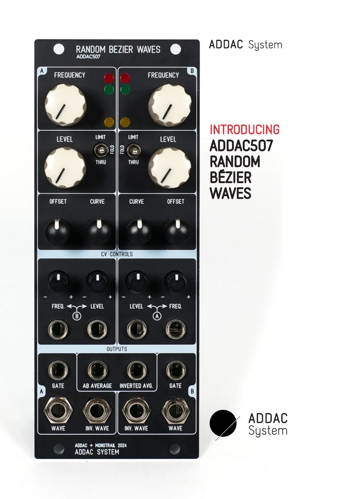
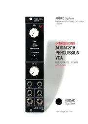
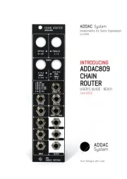
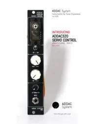
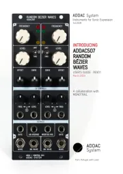
ADDAC System ADDAC507 Manual


Læs gratis den danske manual til ADDAC System ADDAC507 (9 sider) i kategorien Ikke kategoriseret. Denne vejledning er vurderet som hjælpsom af 23 personer og har en gennemsnitlig bedømmelse på 4.9 stjerner ud af 12 anmeldelser. Har du et spørgsmål om ADDAC System ADDAC507, eller vil du spørge andre brugere om produktet?

Side 1/9
March.2024
USER’S GUIDE . REV01
A collaboration with:
MONOTRAIL
ADDAC507
RANDOM
BÉZIER
WAVES
INTRODUCING
From Portugal with Love!
Instruments for Sonic Expression
Est.2009
ADDAC507
RANDOM BÉZIER WAVES USER’S GUIDE
March.2024Revision.01
Welcome to:
page 2ADDAC SYSTEM
WELCOME
This module started with an idea from Rijnder Kamerbeek aka Monotrail,
a straightforward random generator with interpolation between random
points making it something like a complex, ever evolving, LFO
The concept is simple. It contains two identical smooth random voltage
generators. Each has a frequency, level, offset and curve control. The
frequency control sets a steady pace with which bipolar random
voltages are generated. The level control works like an attenuator/VCA
on the output, reaching from max output to closed. The offset allows
shifting the whole wave up and down on the voltage range. Curve
determines the shape of the interpolation.The bipolar activity on the
main outputs as well as gate outputs are visualised with LEDs.
Both Frequency and Level controls have a CV input with attenuator.
When there is nothing patched into the CV inputs, these are internally
connected to the main output of the other channel. This normalization
makes it very easy to add randomization to the frequency or level for
more depth, or of course, add cross-modulation for chaotic voltages.
The output VCAs are usefull to dial in subtle and time-based modulation
without the need for external VCAs. For example, to modulate the
amount over time with an envelope, or use the other generator with
slower speeds to add random changes to the level of a random
voltage.
Both generators also have two other outputs. One is an exact inversion
of the main output, so it responds to the level and CV input. This is
great for stereo or inversed effect patches. The other is a simple pulse
output, here there are two different behaviours, channel A outputs a
pulse at every random generation, channel B acts like a comparator.
Whenever the main is positive this comparator output is a high gate.
And whenever the main output is negative or close to 0, there is no
gate output. Great for random triggers or firing other events like
envelopes.
A couple other outputs are also available and are obtained by averaging
both channel main outputs. The first output is the average while the
second is an inverted average.
Tech Specs:
10HP
4.5cm deep
70mA +12V
40mA -12V
CHANNEL A CHANNEL B


Produkt Specifikationer

Mærke: ADDAC System
Kategori: Ikke kategoriseret
Model: ADDAC507

Har du brug for hjælp?

Hvis du har brug for hjælp til ADDAC System ADDAC507 stil et spørgsmål nedenfor, og andre brugere vil svare dig


Ikke kategoriseret ADDAC System Manualer

Ikke kategoriseret Manualer

Nyeste Ikke kategoriseret Manualer

Neets

Neets Touch Panel 4” Manual

27 September 2025
Sanus

Sanus CFR1610 Manual

27 September 2025
Neets

Neets 310-0111 Manual

27 September 2025
Stiebel Eltron

Stiebel Eltron CNS 75 F Manual

27 September 2025
Duronic

Duronic DM65W1X1 Manual

27 September 2025
Advantech

Advantech ITA-360 Manual

27 September 2025
Advantech

Advantech AIMB-215 Manual

27 September 2025
Advantech

Advantech IPC-220 Manual

27 September 2025