Advantech ASMB-561 Manual

Advantech Bundkort ASMB-561

Læs gratis den danske manual til Advantech ASMB-561 (3 sider) i kategorien Bundkort. Denne vejledning er vurderet som hjælpsom af 2 personer og har en gennemsnitlig bedømmelse på 4.5 stjerner ud af 1.5 anmeldelser. Har du et spørgsmål om Advantech ASMB-561, eller vil du spørge andre brugere om produktet?

Side 1/3
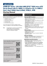
ASMB-561 Startup Manual 1
Before you begin installing your card, please make sure that
the following items have been shipped:
• 1 x ASMB-561 Startup Manual
• 1 x SATA power cables
• 1 x Standard I/O port bracket
• 1 x IO support plate
• 2 x M3 screws for M.2 storage
If any of these items are missing or damaged, please
contact your distributor or sales representative immediately.
Note: AcrobatReaderisrequiredtoviewanyPDFle.
Acrobat Reader can be downloaded at:
https://www.adobe.com/downloads.html
(Acrobat is a trademark of Adobe)
ASMB-561 Series LGA 4844 AMD EPYC™ 8004 micro ATX
Server Board with 6 x DDR5, 4 x PCIe5.0 x16, 5 x USB3.2
Gen1, Dual 10GbE, Dual 2.5GbE, TPM2.0 , IPMI
Startup Manual
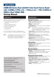
Standard M/B Functions
• CPU: SP6 AMD EPYC™ 8004 8 to 64 cores processors
• BIOS: AMI 256 Mbit SPI BIOS
• System Memory: 6 x DDR5-4800 registered ECC DIMM,
Max. Capacity up to 596 GB
• SATA Interface: 8 via MCIO1&2 ports with SATA 6Gb/s
with MCIO to SATA cables
• M.2 Interface: 2x NVMe M.2 2280 supports PCIe5.0 x4
• Serial Ports: 1 at rear IO, supports RS-232
• Watchdog Timer: 255 level timer intervals
• USB Port: Supports up to 5 x USB 3.2 Gen1 ports (2 rear
ports, 2 ports from onboard 20-pin header and 1*Type-A
on board)
VGA Interface
• Chipset: ASPEED AST2600
• Display Memory: 64 MB
• Resolution: Supports VGA up to resolution 1920x1200
@ 60Hz refresh rate
Ethernet Interface
• Interface: 100/1000/2500 Mbps & 10 GbE Base-T
• Controller: LAN1/2: Intel I226; LAN3/4: Intel X710
Mechanical and Environment
• Dimensions (L x W): 244 x 244 mm (9.6” x 9.6”)
• Power Supply Voltage: +3.3 V, +5 V, ±12 V, +5 V
SB
• Power Consumption (mainboard only, excluding IO
device): •Max.load:+3.3V@0.88A,+5V@2.97A,
+12V @ 0.38 A,+5 VSB @ 0.04 A, +12V_8P @ 13.72 A
• Weight: 0.98 kg (weight of board)
• Operating Temperature: 0 ~ 60°C (depending on CPU)
Specications Packing List
For more information on this and other Advantech
products, please visit our website at:
http://www.advantech.com
For technical support and service, please visit our
support website at:
http://support.advantech.com
Register your products on our website and get 2
months extra warranty for Free at:
http://www.register.advantech.com
This manual is for the ASMB-561 series Rev. A1.
Part No. 2042B56100
Printed in China
1st Edition
August 2025
2 ASMB-561 Startup Manual
The board has a number of jumpers that allow you to con-
gureyoursystemtosuityourapplication.Thetablebelow
lists the function of each of the jumpers and connectors.
Connectors
Label Function
ATXPWR1 ATX 24 Pin main power connector
ATX12V1, ATX12V2 Processor power connector
BH2 For optional battery kit
BIOS_SKT1 BIOS SPI ROM
BMC_SPI1 IPMI ROM
COM1 Serial port: RS-232
CPUFAN0 CPU FAN connector
C0_DIMMA1,
C0_DIMMB1,
C0_DIMMD1,
C0_DIMME1,
C0_DIMMF1,
C0_DIMMH1
DDR5 slot
EX_THR1 Connector for external thermistor
ESPI1 ESPI connector
GPIO1 GPIO connector
HDT1 AMD HDT connector
JFP1, JFP2 Front panel header
LAN1_2,
LAN3_4
RJ-45 2.5GbE LAN connector
RJ-45 10GbE LAN connector
LAN5 IPMI dedicated LAN connector
LAN_LED1 Chassis LAN LED
M2_2280_1 M.2 connector (SATA & PCIe x4)
M2_2280_2 M.2 connector (SATA & PCIe x4)
PMBUS1
PMBUS connector to communi-
cate with power supply
MCIO1
MCIO2
Default SATA0~3
Default SATA4~7
MCIO3
MCIO4
Default Single PCIe x4
Default Single PCIe p2-x4
PCIEX16_SLOT4
~ PCIEX16_SLOT7
PCIE x16 slot (CPU direct)
SMBUS1, SKY_SB1 SMBus header
SPI_CN1 Connector for BIOS update tool
SW1 Intel X710 debug mode setting
SW3, SW4 MCIO Signal setting
SYS_LED1 Chassis System LED
SYSFAN0~SYSFAN4 System FAN connector
Jumpers and Connectors (Cont.)
USB3A1,
USB3C1,
USB 3.2 (Type A) ;
USB 3.2 (Rear port x2)
USB3H1 USB 3.2 port x 2 (20-pin header);
VGA1 VGA connector
Jumper List
Label Function
JCASE1 Chassis case open alarm
JCMOS1 CMOS clear
JWDT1 Watch Dog Reset
PSON1 AT(1-2) / ATX(2-3)
SW3
SW4
Switch OFF(1-4) (SATA)
Switch OFF(2,4) & ON (1,3)
JCMOS1: CMOS Clear Function
Closed pins Result
1-2
Keep CMOS data
2-3 Clear CMOS data
*: Default 1-2
Keep CMOS data Clear CMOS data
SW3 & SW4 Default Setting
Connector Switch Name Port Switch OFF Switch ON
MCI01
SW3
1 SATA MODE PCIE MODE
2 Sideband for SKY_BP Sideband for CXL
MCI02
3 SATA MODE PCIE MODE
4 Sideband for SKY_BP Sideband for CXL
MCI03
SW4
5 5ATA MODE PCIE MODE
6 Sideband for SKY_BP Sideband for CXL
MCI04
7 SATA MODE PCIE MODE
8 Sideband for SKY_BP Sideband for CXL
Declaration of Conformity
The device complies with the requirements in Part 15 of
the FCC rules. Operation is subject to the following two
conditions:
1. This device may not cause harmful interference;
2. This device must accept any interference received,
including interference that may cause undesired opera-
tion.
Jumpers and Connectors


Produkt Specifikationer

Mærke: Advantech
Kategori: Bundkort
Model: ASMB-561

Har du brug for hjælp?

Hvis du har brug for hjælp til Advantech ASMB-561 stil et spørgsmål nedenfor, og andre brugere vil svare dig


Bundkort Advantech Manualer

Bundkort Manualer

Nyeste Bundkort Manualer

ECS

ECS ADLN-I3 IPC Manual

17 September 2025
Asrock

Asrock H810TM-ITX Manual

16 September 2025
ECS

ECS ADLN-I3 Manual

16 September 2025
Foxconn

Foxconn A85GM Manual

13 September 2025
Foxconn

Foxconn H87MX Manual

13 September 2025
Asrock

Asrock W790 WS R2.0 Manual

12 September 2025
Asrock

Asrock Q670M vPro Manual

12 September 2025
Supermicro

Supermicro X13SAW-TLN4F Manual

11 September 2025