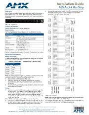
AMX ABS Manual
| Mærke: | AMX |
| Kategori: | stikdase |
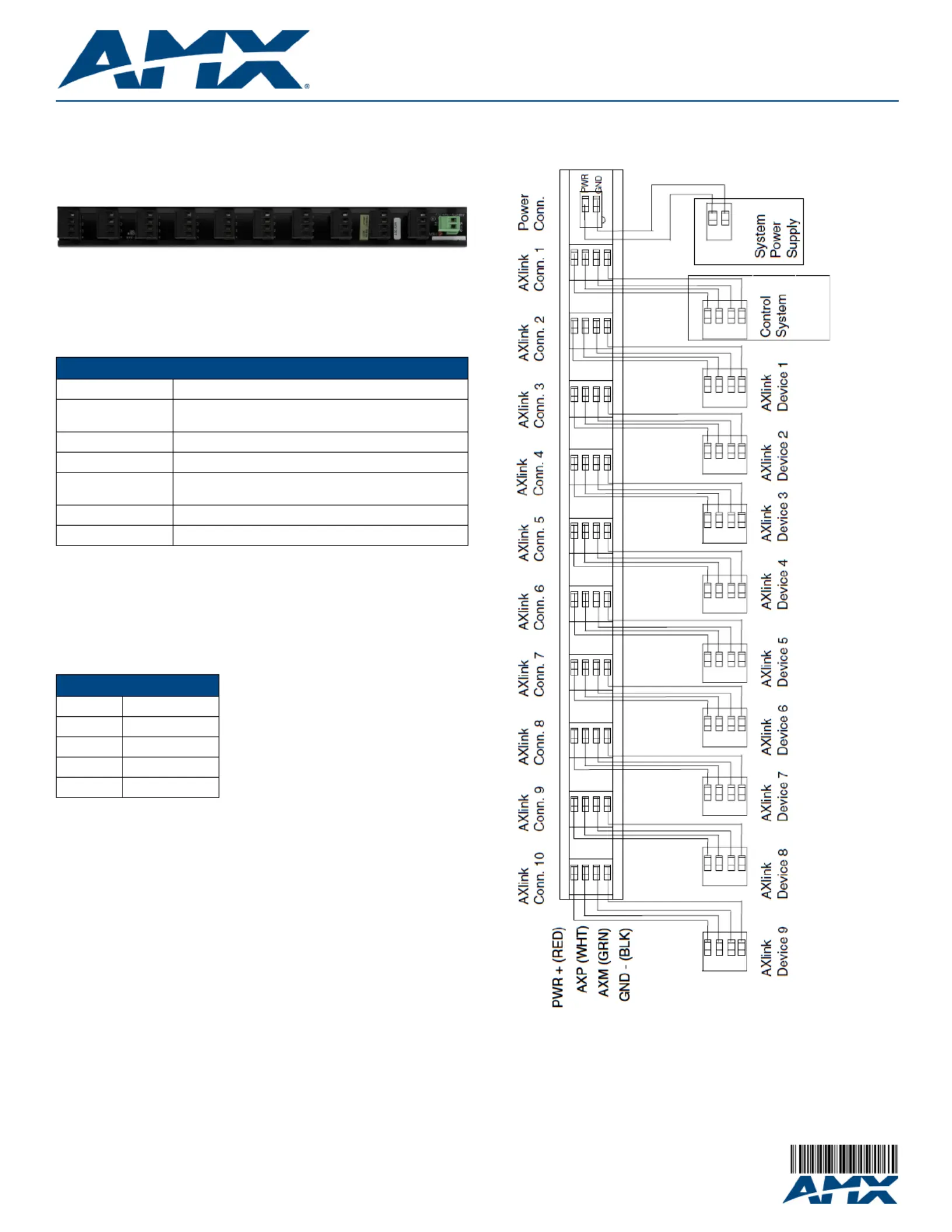
| Model: | ABS |
| Vekselstrømsindgangsspænding: | 12 V |
| Vægt: | 164.42 g |
| Produktfarve: | Sort |
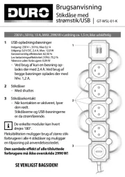
| Dimensioner (BxDxH): | 305 x 32 x 29 mm |
| Stik: | 10 x 4-pin AxLink, 1 x 2-pin |
| AC udgange, antal: | - AC stikkontakt(er) |
| Strøm (maks.): | 10 A |
Har du brug for hjælp?
Hvis du har brug for hjælp til AMX ABS stil et spørgsmål nedenfor, og andre brugere vil svare dig
stikdase AMX Manualer
14 September 2025
stikdase Manualer
- CyberPower
- Gembird
- Lanberg
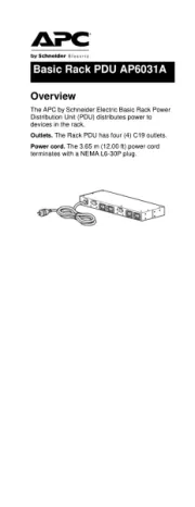
- APC
- EnerGenie
- Vivanco
- GoGen
- Kopp
- Ubiquiti Networks
- Steren
- Essentiel B
- Eaton
- Vevor
- Audiolab
- Huslog
Nyeste stikdase Manualer

5 December 2025

3 December 2025

29 November 2025

6 November 2025
2 November 2025
6 Oktober 2025
14 September 2025
13 September 2025
11 September 2025

10 September 2025