4/8-Port A/V Over Cat 5 Splitter
ATEN and the ATEN logo are trademarks of ATEN International Co., Ltd. All rights reserved. All other
trademarks are the property of their respective owners.
This product is RoHS compliant.
Part No. PAPE-1285-171G Printing Date: 07/2012
VS1204T / VS1208T 4/8-Port A/V Over Cat 5 Splitter User Guide
Répartiteur VS1204T / VS1208T A/V Cat 5 4/8 ports – Guide de l’utilisateur
VS1204T / VS1208T Audio-Video-Splitter Over Cat 5 mit 4/8 Ports Benutzerhandbuch
Repartidor de señal A/V sobre Cat. 5 de 4/8 puertos VS1204T / VS1208T Manual del usuario
The following equipment must be installed on the source device or computer that acts as a
source of VGA/Audio content:
•ATENVE170RA/VOverCat5Receiveror
•ATENVE170RQA/VOverCat5ReceiverwithDeskew
•AVGA,SVGA,XGA,SXGA,WUXGAormultisyncdisplaydeviceorreceiverwithanHDB-
•UseaVGA/AudiocableconnectthesourcedevicetotheVS1204T/VS1208T
•UseCat5ecabletoconnecttheVS1204T/VS1208TtotheVE170R/VE170RQreceiver
Receiver(VE170R/VE170RQ):300m
Receiver(VE170R/VE170RQ)
Le composant suivant doit être installé sur le périphérique source ou sur l’ordinateur agissant
en tant que source du contenu VGA/audio :
•Portdesortieaudio(facultatif)
Périphérique de réception
•RécepteurATENVE170RA/VCat5ou
•RécepteurATENVE170RA/VCat5avecDeskew
•Unpériphériqued’afchageVGA,SVGA,XGA,SXGA,WUXGAoumultisyncouun
récepteur équipé d’un connecteur HDB-15
•Deshaut-parleurs(facultatifs)
•UtilisezuncâbleVGA/audiopourconnecterlepériphériquesourceauVS1204T/VS1208T
•Utilisezuncâbledecatégorie5epourconnecterleVS1204T/VS1208Taurécepteur
Longueur de câble maximale
Récepteur(VE170R/VE170RQ):300m
Récepteur(VE170R/VE170RQ)
Auf den Signalquellen oder Computern, die das VGA-/Audiosignal senden, muss mindestens
Folgendes installiert sein:
•Audioausgangsbuchse(optional)
•ATENVE170RAudio-Video-EmpfängerOverCat5oder
•ATENVE170RQAudio-Video-EmpfängerOverCat5mitSignalkompensation
•EinVGA,SVGA-,XGA-,SXGA-,WUXGA-oderMultisync-Anzeigegerätbzw.
–EmpfangsgerätmitHDB-15-Buchse
•Lautsprecher(optional)
•VerbindenSiedieSignalquellemitdemVS1204T/VS1208T.VerwendenSiedazuein
•VerbindenSiedenVS1204T/VS1208TübereinKat.5e-KabelmitdemVE170R-/
LokalesAnzeigegerät:20m
Empfänger(VE170R/VE170RQ):300m
Receiver(VE170R/VE170RQ)
EntferntesAnzeigegerät:20m
En los dispositivos fuente de señal de audio/VGA u ordenadores que se conectan al equipo
debe estar instalado lo siguiente:
•Puertodesalidadeaudio(opcional)
•ReceptorA/VsobreCat.5ATENVE170Ro
•ReceptorA/VsobreCat.5ATENVE170RQconcompensacióndeseñal
Dispositivo de visualización
•UndispositivodevisualizaciónVGA,SVGA,XGA,SXGA,WUXGAomultisyncoun
receptor con un conector HDB-15
•ConecteeldispositivofuentealVS1204T/VS1208T.Paraello,empleeuncableVGA/
•UtiliceuncabledeCat.5eparaconectarelVS1204T/VS1208TalreceptorVE170R/
Longitudes de cables máximas
Dispositivo fuente de señal
Receptor(VE170R/VE170RQ):300m
Receptor(VE170R/VE170RQ)
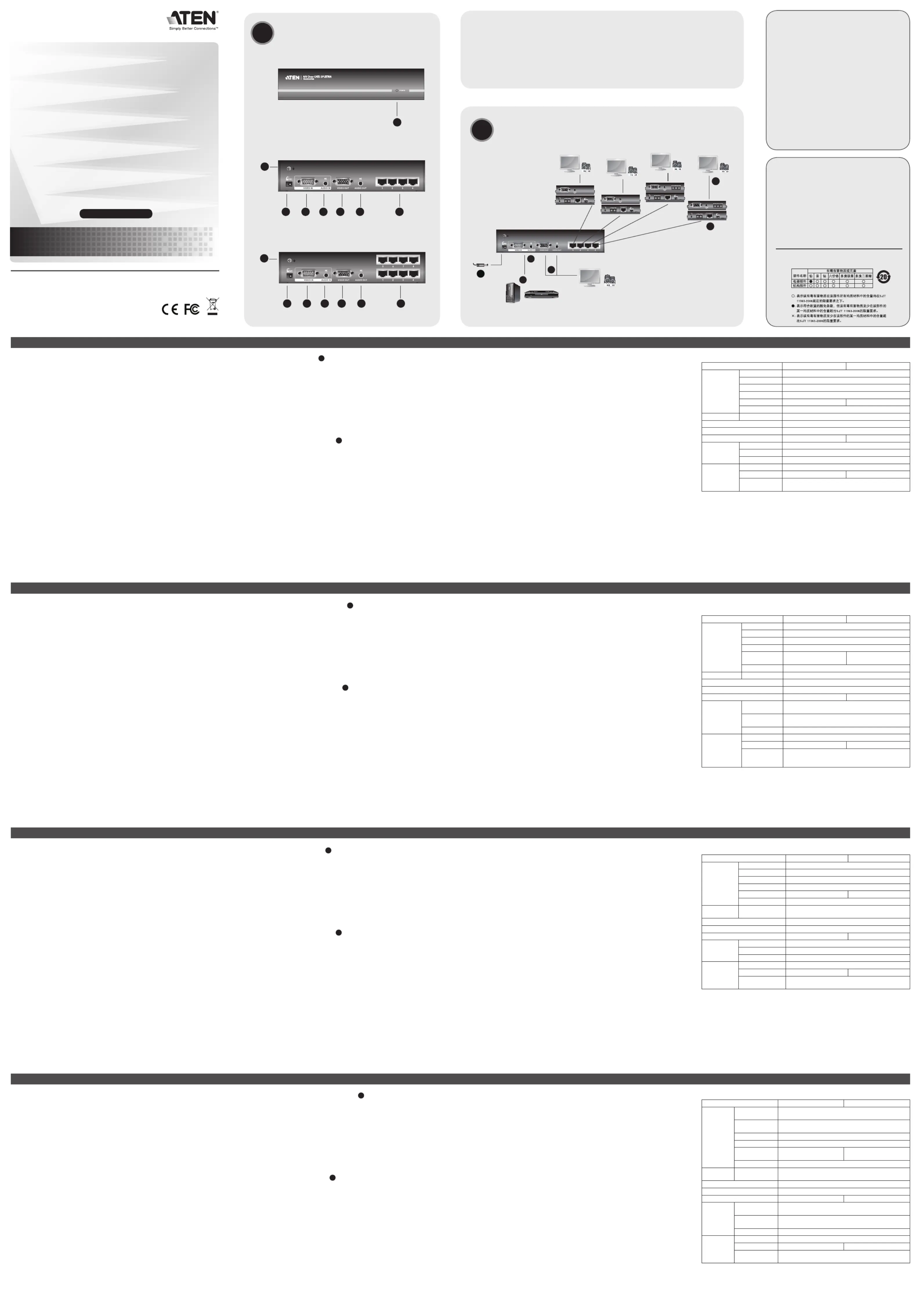
• Beforebeginningtheinstallationprocedure,ensurethatallequipmenttobeconnectedis
• Topreventdamagetoyourinstallation,makesurethatalldevicesareproperlygrounded.
1. Connect one end of a VGA/Audio cable to the video and audio ports on the A/V source
device(e.g.computerorDVDplayer).
2. Connect the other end of the VGA/Audio cable to the Video In and Audio In ports located
on the back panel of the VS1204T / VS1208T.
3.ConnectthelocaldisplayandspeakerstotheVideoOutandAudioOutportsontheunit.
4. Use Cat 5e cable to connect the RJ-45 Unit to Unit Ports on the VS1204T / VS1208T to the
Line In Port on the receiving device*.
5. Plug the remote display’s video and audio cables into the Video Out and Audio Out ports
6. Using the power adapter supplied with this package, connect the unit to an AC power
7. Turn on the source and display devices.
Note: CompatiblereceivingdeviceistheATENVE170R/VE170RQA/VOverCat5
Description de l’appareil
• Avantdedémarrerlaprocédured’installation,assurez-vousquetouslespériphériquesà
• And’éviterd’endommagervotreinstallation,vériezquetouslespériphériquessont
correctement reliés à la terre.
1.Reliezl’unedesextrémitésd’uncâbleaudio/VGAauxportsaudioetvidéodupériphérique
sourceA/V(ordinateuroulecteurDVD,parexemple).
2.Reliezl’autreextrémitéducâbleVGA/audioauxportsd’entréevidéoetaudiosituéssurle
panneau arrière du VS1204T / VS1208T.
3.Branchezl’écranetleshaut-parleurslocauxsurlesportsdesortievidéoetaudiode
4.Utilisezlecâbledecatégorie5epourconnecterlesportsd’unitéàunitéRJ-45duVS1204T
/ VS1208T au port d’entrée de ligne du périphérique de réception*.
5.Branchezlescâblesaudioetvidéodel’écrandistantauxportsdesortieaudioetvidéodu
périphérique de réception.
6. Branchez l’appareil sur une prise de courant à l’aide de l’adaptateur secteur fourni.
7.Allumezlespériphériquesd’afchageetsource.
Remarque: Le périphérique de réception compatible est le Récepteur ATEN VE170R /
7. BuchsenfürDirektverbindungGerätaufGerät
•SchaltenSievorderInstallationalleanzuschließendenGeräteaus.
•UmeineBeschädigungIhrerGerätezuvermeiden,müssenalleGeräteordnungsgemäß
1.VerbindenSiedaseineEndedesVGA/AudiokabelsmitdenGrak-undAudioausgängen
derAV-Signalquelle(z.B.ComputeroderDVD-Player).
2.VerbindenSiedasandereEndedesVGA-/AudiokabelsmitdenGrak-und
AudiosignaleingängenaufderRückseitedesVS1204T/VS1208T.
3.VerbindenSiedenlokalenBildschirmunddielokalenLautsprechermitdemGrak-und
AudiosignalausgängendesGerätes.
4.VerbindenSiedieRJ45-AusgängeGerät-an-GerätdesVS1204T/VS1208TübereinKat.
5e-KabelmitdemLine-In-EingangamEmpfangsgerät*.
5.VerbindenSiedasGrak-unddasAudiokabeldesBildschirmsderGegenstellemitden
Grak-undAudiosignalausgängenamEmpfangsgerät.
6.VerbindenSiedasmitgelieferteNetzteilmitdemGerätundeinerSteckdose.
7.SchaltenSiedieSignalquelleunddasAnzeigegerätein.
Hinweis:ZudiesemGerätistdieVE170R/VE170RQAudio-Video-EmpfängerOverCat5
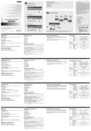
Presentación del hardware
1. IndicadorLEDdealimentación
2. Entradadealimentación
3. Puertodeentradadeseñalgráca
5. Salidadeseñalgráca
7. Puertos de unidad a unidad
•Antesdeiniciarelprocesodeinstalación,asegúresedequetodoslosequiposquevayaa
•Paraevitardañosenlosdispositivos,veriquequetodosellosesténconectadosatierra
1.Conecteunextremodelcabledeaudio/VGAalospuertosdeaudioygrácodeldispositivo
fuenteA/V(p.ej.ordenadororeproductordeDVD).
2. Conecte el otro extremo del cable de audio/VGA a los puertos de entrada de audio y
grácaubicadosenelpanelposteriordelVS1204T/VS1208T.
3.Conectelapantallaylosaltavoceslocalesalospuertosdesalidagrácaydeaudiodela
4.UtiliceuncabledeCat.5eparaconectarlospuertosdesalidadelíneaRJ-45(Line-Out)
delVS1204T/VS1208Talpuertodeentradadelínea(Line-In)delreceptorencuestión*.
5.Conecteloscablesdeaudioygrácodelapantalladistantealospuertosdesalidade
audioyseñalgrácadelreceptor.
6.Conectelaunidadaunatomaeléctricamedianteeladaptadordealimentaciónincluido.
7.Enciendalosdispositivosdevisualizaciónyfuente.
Nota: EldispositivocompatibleeselReceptorA/VsobreCat.5VE170R/VE170RQde
Din Rail and Wall Mounting
To mount the VS1204T / VS1208T on a din rail do the following:
•Usingthescrewsprovidedwiththispackage,screwthemountingbracketintothebottom
oftheunit,thenscrewtheprovidedclippersintothebracketandnallycliptheVS1204T/
To mount the VS1204T / VS1208T on a wall do the following:
•Usingthescrewsprovidedwiththispackage,screwthemountingbracketintothebottomof
the unit, and then screw the bracket into the wall.
Montage au mur ou sur rail
Pour monter le VS1204T / VS1208T sur rail, procédez comme suit :
•Vissezlesupportdemontagesurlapartieinférieuredel’unité(àl’aidedesvisfournies).
Vissezensuitelesattachesfourniessurlesupport,puisxezleVS1204T/VS1208Taurail.
Pour monter le VS1204T / VS1208T au mur, procédez comme suit :
•Vissezlesupportdemontagesurlapartieinférieuredel’appareil(àl’aidedesvisfournies),
puisxezlesupportaumur.
Hutschienen- und Wandmontage
UmdenVS1204T/VS1208TaufeineHutschienezusetzen,gehenSiefolgendermaßenvor:
•VerwendenSiediemitgeliefertenSchrauben,umdenMontagerahmenaufdieUnterseite
desGeräteszuschrauben.AnschließendbringenSiediemitgeliefertenKlammernanund
setzen den VS1204T / VS1208T auf die Hutschiene.
UmdenVS1204T/VS1208TanderWandzumontieren,gehenSiefolgendermaßenvor:
•VerwendenSiediemitgeliefertenSchrauben,umdenMontagerahmenaufdieUnterseite
desGeräteszuschrauben.AnschließendbringenSiedenRahmenanderWandan.
Montaje sobre raíl o en la pared
ParamontarelVS1204T/VS1208Tsobreunraíl,procedacomoseindicaacontinuación:
•Atornilleelmarcodemontajeenlaparteinferiordelaunidad(conlostornillosincluidos),
luegoatornillelasjacionesincluidasenelmarcoyjeelVS1204T/VS1208Talraíl.
ParamontarelVS1204T/VS1208Tenlapared,procedacomoseindicaacontinuación:
•Atornilleelmarcodemontajeenlaparteinferiordelaunidad(conlostornillosincluidos)y
luegojeelmarcoalapared.
Video In 1xHDB-15Male(Blue)
Video Out 1xHDB-15Female(Blue)
Audio In 1xMiniAudioJackFemale(Green)
Audio Out 1xMiniAudioJackFemale(Green)
Unit to Unit 4 x RJ-45 Female 8 x RJ-45 Female
Power Consumption DC5.3V,1.33W DC5.3V,1.64W
Humidity 0–80% RH, Non-condensing
Caractéristiques techniques
Entrée vidéo 1connecteurHDB-15mâle(bleu)
Sortie vidéo 1connecteurHDB-15femelle(bleu)
Entrée audio 1mini-connecteuraudiofemelle(vert)
Sortie audio 1mini-connecteuraudiofemelle(vert)
Alimentation 1 prise d’alimentation CC
Voyants Alimentation 1voyant(vert)
Consommation électrique 5,3Vc.c.,1,33W 5,3Vc.c.,1,64W
Humidité Humidité relative de 0 à 80 %, sans condensation
Grakeingänge 1xHDB-15Männlein(blau)
Grakausgänge 1xHDB-15Weiblein(blau)
Audio-Eingänge 1xMini-Audio-Buchse,Weiblein(grün)
Audio-Ausgang 1xMini-Audio-Buchse,Weiblein(grün)
GerätanGerät 4xRJ-45Weiblein 8xRJ-45Weiblein
Stromversorgung 1 x Stromeingangsbuchse
Grak 1920 x 1200 bei 60Hz
Stromverbrauch 5,3V=,1,33W 5,3V=,1,64W
Betriebstemperatur 0-50 °C
Lagertemperatur -20-60 °C
Feuchtigkeit 0 -80% rel. Luftfeuchte, nicht kondensierend
1conectorHDB-15macho(azul)
1conectorHDB-15hembra(azul)
Entra da de audio 1conectorminiaudiohembra(verde)
Salida de audio 1conectorminiaudiohembra(verde)
4 conectores RJ-45 hembra 8 conectores RJ-45 hembra
Alimentación 1 toma de c.c.
Señalgráca 1920 x 1200 a 60 Hz
Consumo 5,3Vc.c.,1,33W 5,3Vc.c.,1,64W
Humedad 0 a 80% de HR, sin condensar
The following contains information that relates to
This equipment has been tested and found to comply with
the limits for a Class B digital device, pursuant to Part 15
of the FCC Rules. These limits are designed to provide
reasonable protection against harmful interference in a
residential installation. This equipment generates, uses
and can radiate radio frequency energy, and if not installed
and used in accordance with the instruction manual, may
cause interference to radio communications. However,
there is no guarantee that interference will not occur in a
particular installation. If this equipment does cause harmful
interference to radio or television reception, which can be
determined by turning the equipment off and on, the user
is encouraged to try to correct the interference by one or
more of the following measures:
•Reorientorrelocatethereceivingantenna;
•Increasetheseparationbetweentheequipmentand
•Connecttheequipmentintoanoutletonacircuitdifferent
fromthatwhichthereceiverisconnected;
•Consultthedealer/anexperiencedradio/television
A. VS1204T/VS1208T Front View
Allinformation,documentation,andspecicationscontainedinthismediaaresubjecttochangewithoutprior
noticationbythemanufacturer.Pleasevisitourwebsitetondthemostuptodateversion.
1 VS1204T or VS1208T A/V Over Cat 5 Splitter