Thank you for purchasing this Audio-Technica product. Before using the
product, read through this user manual to ensure that you will use the
product correctly. Please keep this manual for future reference.
•Keep the plastic bag provided with the product out of the reach
of small children and away from open flames to avoid accidents
•Keep the product out of the reach of small children to avoid
accidents or malfunction.
•Do not put the product in a location where it is exposed to direct
sunlight, near heating devices, or in places with high
temperatures, high humidity, or high concentrations of dust to
•Do not touch the product’s cantilever and stylus tip to avoid
•Do not attempt to disassemble or modify the product to avoid
•Do not subject the product to strong impact to avoid
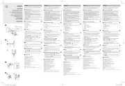
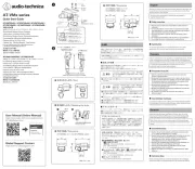
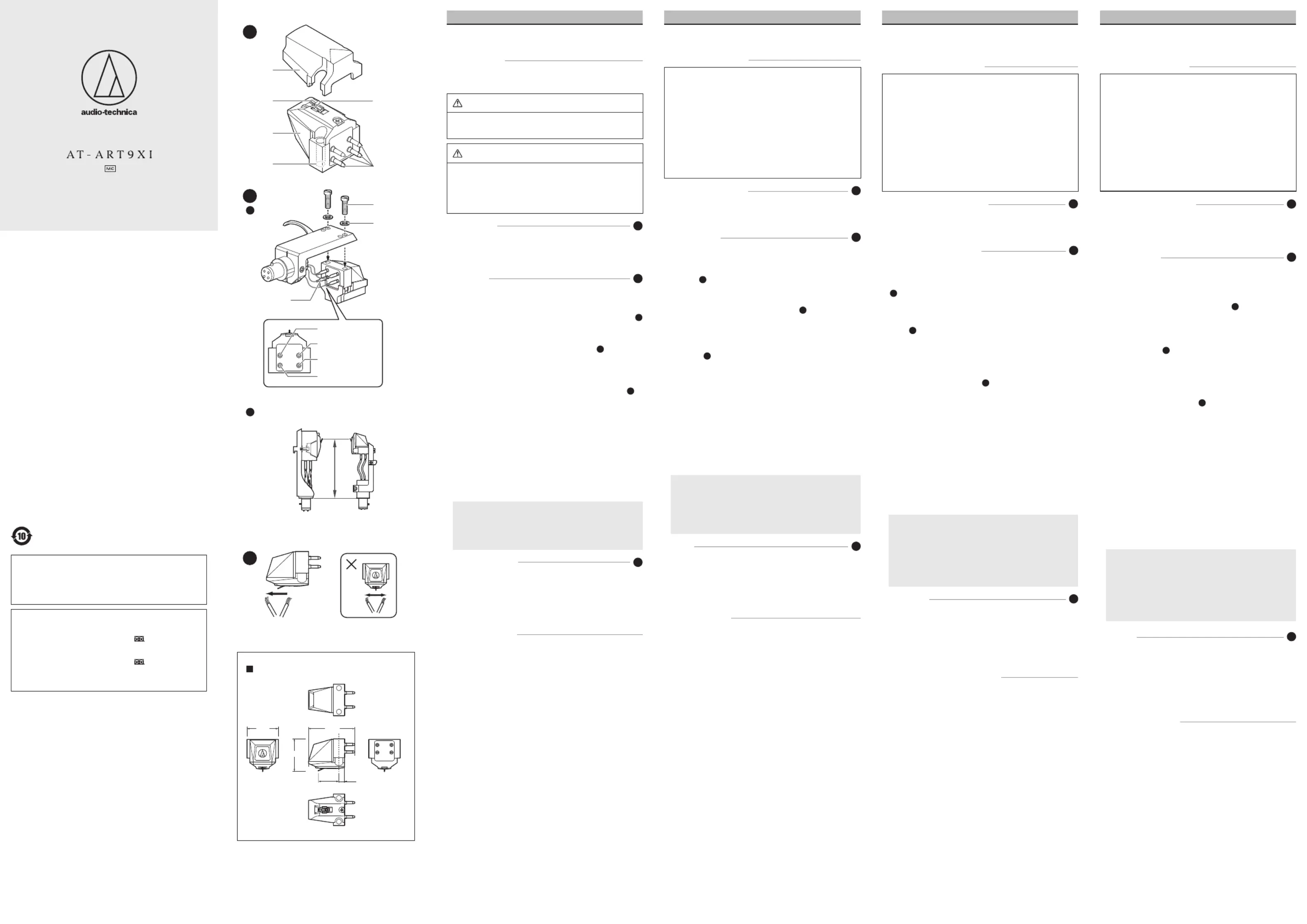
Become familiar with each part before using the product.
• The product is extremely delicate. Handle it with sufficient care.
• This product can be mounted only for the through hole type headshell
or headshell-integrated tonearm.
1. Mount the product onto the headshell or headshell-integrated
• Mount the cartridge with the protector on to avoid damaging the
cantilever and the stylus tip.
• Temporarily tighten the screws.
2. Connect the lead tips, noting output polarity.
• Connect headshell lead tips to the product output terminals (as
• Never apply heat (from solder, etc.) to the output terminals.
3. Remove the protector from the product.
4. Determine the correct position for installing the product (adjust
• Adjust overhang following the instructions in the tonearm’s,
turntable’s, or headshell’s user manual.
If you are unsure, align the stylus tip to the cartridge originally
attached to the tonearm (as shown in the figure).
• Finish tightening screws, making sure there is a balance between
5. Adjust tracking force.
• Confirm the tracking force for the product in “Specifications.”
• Do not apply stylus pressure unnecessarily. It may not only
damage the record and stylus but impair audio quality.
6. Adjust tonearm height.
• Adjust the height so that the bottom surface of the headshell and
the record surface are parallel, as seen from the side. An improper
tonearm height may cause the body of the product to make
contact with the record and could impair audio quality or damage
• You need a transformer, head amplifier, or standalone phono
equalizer to connect to a preamplifier/amplifier. If the
preamplifier/amplifier has a phono input (MC position), it may be
used as it is. However to fully take advantage of this product’s
audio quality, using a step-up transformer (sold separately), head
amplifier (sold separately), or phono equalizer (sold separately) is
recommended. For connection instructions, refer to the user
manual of the equipment you are connecting.
• Use the brush provided to remove dirt and dust on the stylus tip.
• Always move the brush in the direction in which the record rotates.
• A stylus cleaner (sold separately) is recommended to remove
• When the product is removed from the tonearm, do not forget to
attach the protector and store the product away from the amplifier
and other heat sources and magnetic materials.
Frequency response: 20 to 50,000 Hz
Output voltage: 0.5 mV (1 kHz, 5 cm/sec.)
Channel separation: 30 dB (1 kHz)
Output balance: 0.5 dB (1 kHz)
Tracking force: 1.6 to 2.0 g (1.8 g standard)
Coil impedance: 12 ohms (1 kHz)
Recommended load impedance: ≥ 100 ohms (when head amplifier connected)
Coil inductance: 25 μH (1 kHz)
Static compliance: 25 × 10
Dynamic compliance: 15 × 10
Stylus: Nude Special Line Contact
Stylus curvature radius: 1.5×0.28 mil
Cantilever: 0.28 mm (0.011”) diameter solid boron
Vertical tracking angle: 20°
Dimensions: 17.3 mm (0.68”) × 16.8 mm (0.66”) × 25.0 mm (0.98”)
Accessories: Non-magnetic screwdriver, Brush, Washer × 2, Cartridge
installation screws (M2.6) (5.0 mm (0.20”) × 2, 8.0 mm (0.31”) ×
2, 10.0 mm (0.39”) × 2, 12.0 mm (0.47”) × 2), Protector
For product improvement, the product is subject to modification without
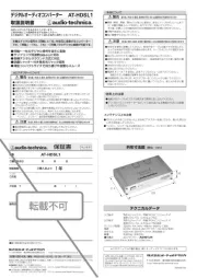
Make this distance as exact as possible.
White (left channel / ) +
Green (right channel / )-
お買い上げありがとうございます。ご使用の前にこの取扱説明書を必ずお読み
のうえ、正しくご使用ください。また、いつでもすぐ読める場所に保管しておい
本製品は安全性に充分な配慮をして設計をしていますが、使いかたを誤ると
事故を未然に防ぐために下記の内容を必ずお守りください。
この表示は「取り扱いを誤った場合、使用者が死亡または重傷を負
•同梱のポリ袋は幼児の手の届く所や火のそばに置かないでください。
•幼児の手の届く所に置かないでください。事故や故障の原因になります。
この表示は「取り扱いを誤った場合、使用者が傷害を負う、または
物的損害が発生する可能性があります」を意味しています
•直射日光の当たる場所、暖房器具の近く、高温多湿やほこりの多い場所
に置かないでください。故障や不具合の原因になります。
•カンチレバー、スタイラスチップは指で触れないでください。故障の原因
•分解や改造はしないでください。故障の原因になります。
•強い衝撃を与えないでください。故障の原因になります。
ご使用になる前に、本製品の各部を確認してください。
•本製品は大変デリケートです。取り扱いには充分注意して使用してください。
•本製品は貫通穴タイプのヘッドシェルまたはシェル一体型トーンアームのみ
本製品をヘッドシェルまたはシェル一体型トーンアームに取り付けます。
•カンチレバー、スタイラスチップを傷めないよう、プロテクターをかぶせた
出力端子の極性に注意して、リードチップを接続します。
•ヘッドシェルのシェルリードチップと本製品の出力端子を、図のようにリ
•出力端子にはハンダなどの熱を絶対に加えないでください。
本製品の取り付け位置を正確に決めます(オーバーハングの調整)。
•トーンアーム、ターンテーブルまたはヘッドシェルの取扱説明書に従って、
オーバーハングの調整をします。不明な場合は、図のようにお手持ちのタ
ーンテーブルに最初から付いているカートリッジの針先位置に合わせてく
•本製品の針圧は「テクニカルデータ」で確認してください。
•必要以上に針圧をかけて使用しないでください。レコードや針を傷めるだ
•ヘッドシェルの底面とレコード面が横から見て平行になるように、高さを
調整してください。トーンアームの高さが適切でないと、本製品のボディが
レコードに当たり、音質が劣化したり、レコードに傷が付いたりすることが
•アンプとの接続にはトランスかヘッドアンプ、または単体フォノイコライ
ザーが必要です。アンプにフォノ(PHONO)入力(MCポジション)があ
る場合はそのまま使用することもできますが、本製品の音質を活かす
ため、昇圧トランス(別売)かヘッドアンプ(別売)、またはフォノイコライ
ザー(別売)の使用をおすすめします。接続については、接続する機器の
•スタイラスチップにごみや汚れが付着した場合は、必ず付属の専用ブラシで
•ブラシは必ずレコードの進行方向に動かしながら使用してください。
•スタイラスチップの汚れがひどい場合は、スタイラスクリーナー(別売)を使
•本製品をトーンアームから取り外したときは忘れずにプロテクターを取り付
け、アンプなどの熱源や磁性体から離して保管してください。
出力電圧:0.5mV(1kHz、5cm/sec.)
外形寸法:17.3mm×16.8mm×25.0mm(H×W×D)
付属品:非磁性体ドライバー、ブラシ、ワッシャー ×2、カートリッジ取り付けビス(M2.6)
(5.0mm×2、8.0mm×2、10.0mm×2、12.0mm×2)、プロテクター
本製品をご家庭用として、取扱説明や接続・注意書きに従ったご使用にお
いて故障した場合、保証書記載の期間・規定により無料修理をさせていた
だきます。修理ができない製品の場合は、交換させていただきます。お買
い上げの際の領収書またはレシートなどは、保証開始日の確認のために
保証書と共に大切に保管し、修理などの際は提示をお願いします。
お問い合わせ先(電話受付 / 平日 9:00 ~17:30)
製品の仕様・使いかたや修理・部品のご相談は、お買い上げのお店または
当社窓口およびホームページのサポートまでお願いします。
(携帯電話・PHS などのご利用は 03-6746-0211)
FAX:042-739-9120 E メール:support@audio-technica.co.jp
(携帯電話・PHS などのご利用は 03-6746-0212)
servicecenter@audio-technica.co.jp
●ホームページ(サポート) www.audio-technica.co.jp/atj/support/
112301671-01-01 ver.1 2020.02.15
生产标准:GB8898-2011, GB/T13837-2012
Audio-Technica Corporation
2-46-1 Nishi-naruse, Machida, Tokyo 194-8666, Japan
©2020 Audio-Technica Corporation
Global Support Contact: www.at-globalsupport.com
〒194-8666 東京都町田市西成瀬2-46-1
Nous vous remercions d’avoir fait l’acquisition de ce produit Audio-
Technica. Avant de l’utiliser, lisez entièrement ce manuel de l’utilisateur
afin de vous assurer que vous utiliserez correctement le produit. Veuillez
conserver ce manuel pour référence future.
•Gardez le sac plastique fourni avec le produit hors de portée des
jeunes enfants et éloigné de flammes afin d’éviter tout accident
•Gardez le produit hors de portée des jeunes enfants afin d’éviter
tout accident ou dysfonctionnement.
•Ne placez pas le produit dans un endroit où il est exposé aux
rayons directs du soleil, à proximité d’appareils de chauffage, ou
dans des lieux où règnent des températures élevées, une
humidité élevée ou des poussières en forte concentration pour
éviter tout dysfonctionnement.
•Ne touchez pas le cantilever et la pointe de lecture du produit
pour éviter tout dysfonctionnement.
•Ne tentez pas de démonter ou d’apporter des modifications au
produit afin d’éviter tout dysfonctionnement.
•Ne soumettez pas le produit à de forts impacts afin d’éviter tout
Familiarisez-vous avec chaque élément avant d’utiliser le produit.
• Le produit est extrêmement délicat. Manipulez-le avec précaution.
• Ce produit peut uniquement être fixé sur un porte-cellule ou un bras à
porte-cellule intégré à points de fixation traversants.
1. Fixez le produit au porte-cellule ou au bras à porte-cellule intégré.
• Montez la cellule avec la protection afin d’éviter d’endommager le
cantilever et la pointe de lecture.
• Serrez provisoirement les vis.
2. Raccordez les extrémités de fils en faisant attention à la polarité de
• Raccordez les extrémités de fils du porte-cellule aux bornes de
sortie du produit (comme indiqué sur l’illustration).
• Ne chauffez jamais (à l’aide d’un fer à souder etc.) les bornes de
3. Enlevez la protection du produit.
4. Déterminez la position correcte pour l’installation du produit
(réglage de l’avant de la cellule).
• Réglez l’avant de la cellule en suivant les instructions du manuel de
l’utilisateur du bras de lecture, de la platine ou du porte-cellule.
En cas de doute, alignez la pointe de lecture à la cellule fixée
initialement au bras de lecture (comme indiqué sur l’illustration).
• Terminez le serrage des vis en vous assurant que les côtés droit et
gauche sont en équilibre.
5. Réglez la force d’appui.
• Vérifiez la force d’appui du produit en vous référant aux
« Caractéristiques techniques ».
• N’appliquez pas inutilement de pression sur la pointe. Cela peut
non seulement endommager le disque et la pointe mais également
nuire à la qualité audio.
6. Réglez la hauteur du bras de lecture.
• Réglez la hauteur de sorte que la surface du dessous du
porte-cellule et la surface du disque soient parallèles, comme vu de
profil. Une hauteur du bras de lecture incorrecte peut entraîner un
contact du corps du produit avec le disque et peut altérer la qualité
audio ou endommager le disque.
• Un transformateur, un amplificateur ou un égaliseur phono
autonome est nécessaire pour le raccordement à un pré-
amplificateur/amplificateur. Si le pré-amplificateur/amplificateur
possède une entrée phono (position MC), il peut être utilisé tel
quel. Néanmoins, pour profiter pleinement de la qualité audio de
ce produit, l’utilisation d’un transformateur élévateur de tension
(vendu séparément), d’un amplificateur (vendu séparément) ou
d’un égaliseur phono (vendu séparément) est recommandée. En
ce qui concerne les instructions de raccordement, reportez-vous
au manuel de l’utilisateur pour l’équipement que vous raccordez.
• Utilisez la brosse fournie pour enlever les impuretés et poussières de
• Déplacez toujours la brosse dans le sens de rotation du disque.
• Une solution nettoyante pour pointe de lecture (vendue séparément)
est recommandé pour enlever les impuretés persistantes.
• Lorsque le produit est retiré du bras de lecture, n’oubliez pas de fixer
la protection et d’entreposer le produit loin de l’amplificateur et
d’autres sources de chaleur et matériaux magnétiques.
■Caractéristiques techniques
Réponse en fréquence : 20 Hz à 50000 Hz
Tension de sortie : 0,5 mV (1 kHz, 5 cm/s.)
Séparation entre les canaux : 30 dB (1 kHz)
Équilibre des canaux : 0,5 dB (1 kHz)
Force d’appui : 1,6 à 2,0 g (1,8 g en standard)
Impédance de la bobine : 12 ohms (1 kHz)
Impédance de charge recommandée : ≥ 100 ohms (lorsque l’amplificateur est
Inductance de la bobine : 25 μH (1 kHz)
Compliance statique : 25 × 10
Compliance dynamique : 15 × 10
Pointe de lecture : Nue, Special Line Contact
Rayon de courbure de la pointe : 1,5×0,28 mil
Cantilever : Bore solide de 0,28 mm de diamètre
Angle de lecture vertical : 20°
Dimensions: 17,3 mm × 16,8 mm × 25,0 mm (H × L × P)
Accessoires : Tournevis non magnétique, Brosse, Rondelle × 2, Vis de fixation
de la cellule (M2,6) (5,0 mm × 2, 8,0 mm × 2, 10,0 mm × 2, 12,0
À des fins d’amélioration, le produit peut être modifié sans préavis.
Vielen Dank für den Kauf dieses Audio-Technica-Produktes. Lesen Sie
vor dem Gebrauch dieses Produktes die Bedienungsanleitung für eine
ordnungsgemäße Nutzung. Bitte bewahren Sie diese Anleitung zum
späteren Nachschlagen auf.
•Bewahren Sie den Plastikbeutel, der dem Produkt beiliegt,
außerhalb der Reichweite von kleinen Kindern auf und fern von
offenen Feuern, um Unfälle oder Brände zu verhindern.
•Bewahren Sie das Produkt außerhalb der Reichweite von kleinen
Kindern auf, um Unfälle oder Fehlfunktionen zu vermeiden.
•Platzieren Sie das Produkt zur Vermeidung einer Fehlfunktion
nicht an einem Ort, an dem es direktem Sonnenlicht ausgesetzt
ist, in der Nähe von Heizgeräten oder an Orten, an denen eine
hohe Temperatur oder hohe Luftfeuchtigkeit herrscht oder viel
•Berühren Sie nicht den Nadelträger oder die Nadelspitze um eine
Fehlfunktion zu vermeiden.
•Versuchen Sie zur Vermeidung einer Fehlfunktion nicht das
Produkt auseinanderzubauen oder zu modifizieren.
•Setzen Sie das Produkt zur Vermeidung einer Fehlfunktion
keinen starken Stößen aus.
Machen Sie sich vor der Verwendung des Produktes mit der
Bezeichnung der Teile vertraut.
2. Spitze der Abtastnadel
4. Gewindebohrungen (M2,6)
• Das Produkt ist äußerst fragil. Handhaben Sie es mit größter Sorgfalt.
• Dieses Produkt kann nur an einem Tonabnehmerkopf mit
Montagebohrungen oder einen entsprechenden Tonarm mit
integriertem Tonabnehmerkopf montiert werden.
1. Befestigen Sie das Produkt an Ihrem Tonabnehmerkopf oder
Tonarm mit integriertem Tonabnehmerkopf.
• Befestigen Sie das Tonabnehmersystem mit angebrachter
Schutzkappe, um eine Beschädigung des Nadelträgers und der
Nadelspitze zu vermeiden.
• Ziehen Sie die Schrauben vorübergehend an.
2. Verbinden Sie die Drahtenden unter Beachtung der
• Verbinden Sie die Drahtenden des Tonabnehmerkopfs mit den
Ausgangsklemmen (wie in der Abbildung gezeigt).
• Setzen Sie die Ausgangsklemmen keiner Wärme aus (von
3. Entfernen Sie die Schutzkappe vom Produkt.
4. Bestimmen Sie die richtige Position für die Installation des
Produktes (Überhang justieren).
• Justieren Sie den Überhang gemäß den Anweisungen in der
Bedienungsanleitung des Tonarms, Plattenspielers oder
Wenn Sie unsicher sein sollten, richten Sie die Spitze der
Abtastnadel an dem ursprünglich am Tonarm befestigten
Tonabnehmer aus (wie in der Abbildung dargestellt).
• Ziehen Sie die Schrauben endgültig an und stellen Sie sicher, dass
die linke und rechte Seite gleichmäßig angezogen ist.
5. Justieren Sie die Auflagekraft.
• Prüfen Sie die Auflagekraft des Produkts unter „Technische Daten“.
• Üben Sie keinen unnötigen Druck auf die Nadel aus. Dadurch kann
nicht nur die Schallplatte und die Nadel beschädigt sondern auch
die Audioqualität beeinträchtigt werden.
6. Justieren Sie die Tonarmhöhe.
• Justieren Sie die Höhe so, dass die Unterseite des
Tonabnehmerkopfs und die Schallplattenoberfläche parallel sind,
wie von der Seite aus betrachtet. Eine falsche Tonarmhöhe kann
eventuell dazu führen, dass das Produktgehäuse die Schallplatte
berührt, wodurch die Audioqualität beeinträchtigt oder die
Schallplatte beschädigt wird.
• Sie benötigen einen Transformator, Vorverstärker oder
eigenständigen Phono-Equalizer, um einen Vorverstärker/
Verstärker anzuschließen. Wenn der Vorverstärker/Verstärker
über einen Phono-Eingang (MC-Position) verfügt, kann er so
verwendet werden. Um die Audioqualität des Produktes voll
auszuschöpfen, wird die Nutzung eines Aufwärtstransformators
(separat erhältlich), Vorverstärkers (separat erhältlich) oder
Phono-Equalizers (separat erhältlich) empfohlen. Einzelheiten
zum Anschluss finden Sie in der Bedienungsanleitung des
• Verwenden Sie den mitgelieferten Pinsel, um Schmutz und Staub von
der Spitze der Abtastnadel zu entfernen.
• Bewegen Sie den Pinsel immer in Drehrichtung der Schallplatte.
• Ein Abtastnadelreiniger (separat erhältlich) wird für die Entfernung
von hartnäckigem Schmutz empfohlen.
• Wenn das Produkt vom Tonarm abgenommen wird, muss unbedingt
die Schutzkappe angebracht werden und das Produkt fern von
Verstärkern und anderen Wärmequellen sowie magnetischen Teilen
Frequenzgang: 20 bis 50.000 Hz
Ausgangsspannung: 0,5 mV (1 kHz, 5 cm/Sek.)
Kanaltrennung: 30 dB (1 kHz)
Ausgangsbalance: 0,5 dB (1 kHz)
Auflagekraft: 1,6 bis 2,0 g (1,8 g Standard)
Spulenimpedanz: 12 Ohm (1 kHz)
Empfohlene Lastimpedanz: ≥ 100 Ohm (bei angeschlossenem Vorverstärker)
Spuleninduktivität: 25 μH (1 kHz)
Statische Compliance: 25 × 10
Dynamische Compliance: 15 × 10
Abtastnadel: Special Line Contact, nackt
Rundungsradius der Nadel: 1,5×0,28 mil
Nadelträger: Massiver Bor-Nadelträger mit einem Durchmesser von 0,28 mm
Vertikaler Abtastwinkel: 20°
Abmessungen: 17,3 mm × 16,8 mm × 25,0 mm (H × B × T)
Zubehör: Nichtmagnetischer Schraubendreher, Pinsel, Abstandshalter 2×,
Tonabnehmer-Befestigungsschrauben (M2,6) (5,0 mm × 2, 8,0 mm ×
2, 10,0 mm × 2, 12,0 mm × 2), Schutzkappe
Produktänderungen zu Zwecken der Produktverbesserung ohne Ankündigung
デュアルムービングコイル(MC)ステレオカートリッジ
Dual Moving Coil Stereo Cartridge
Cellule Stéréo à Double Bobinage Mobile
Stereo-tonabnehmersystem mit Doppel-drehspule
Testina Fonografica Stereo a Doppio Magnete Mobile
Cartucho estéreo de doble bobina móvil
Cápsula Estéreo de Bobina Móvel Dupla
Головка звукоснимателя стереофоническая с двойной