Funk Schaltaktor 1fach UP, Funk
Tastaktor UP
Sicherheitshinweise
Einbau und Montage elektrischer Geräte dürfen
nur durch Elektrofachkräfte erfolgen.
Schwere Verletzungen, Brand oder Sachschäden
möglich. Anleitung vollständig lesen und
beachten.
Gefahr durch elektrischen Schlag. Gerät ist nicht
zum Freischalten geeignet.
Gefahr durch elektrischen Schlag. Vor Arbeiten
an Gerät oder Last freischalten. Dabei alle
Leitungsschutzschalter berücksichtigen, die
gefährliche Spannungen an Gerät oder Last
liefern.
Gefahr durch elektrischen Schlag an der SELV/
PELV-Installation. Nicht zum Schalten von SELV/
PELV-Spannungen geeignet.
Brandgefahr. Nicht zum Schalten eines zweiten
Außenleiters geeignet.
Die Funk-Übertragung erfolgt auf einem nicht
exklusiv verfügbaren Übertragungsweg und ist
daher nicht geeignet für Anwendungen aus dem
Bereich der Sicherheitstechnik, wie z. B. Not-
Aus, Notruf.
Gefahr durch elektrischen Schlag. Antenne ist
basisisoliert. Nicht aus der Gerätedose
herausführen.
Antenne nicht kürzen, verlängern oder
abisolieren. Gerät kann beschädigt werden.
Diese Anleitung ist Bestandteil des Produktes
und muss beim Endkunden verbleiben.
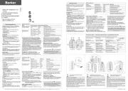
Geräteaufbau
Bild 1
(1) Schalt-/Tastaktor
(2) LED
(3) Programmiertaste
(4) Antenne
Funktion
Systeminformation
Die Sendeleistung, die Empfangscharakteristik und
die Antenne dürfen aus gesetzlichen Gründen nicht
verändert werden.
Das Gerät darf in allen EU- und EFTA-Staaten
betrieben werden.
Die Konformitätserklärung steht auf unserer Internet-
Seite.
Die Reichweite eines Funksystems aus Sender und
Empfänger hängt von verschiedenen Gegebenheiten
ab.
Durch die Wahl des bestmöglichen Montageortes
unter Berücksichtigung der baulichen
Gegebenheiten kann die Reichweite des Systems
optimiert werden.
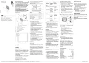
Bild 2: Reduzierte Reichweite durch bauliche
Hindernisse
Beispiele für die Durchdringung von
verschiedenen Materialien:
Material Durchdringung
Holz, Gips,
Gipskartonplatte
ca. 90 %
Ziegelstein,
Pressspanplatte
ca. 70 %
armierter Beton ca. 30 %
Metall, Metallgitter ca. 10 %
Regen, Schnee ca. 1-40 %
Bestimmungsgemäßer Gebrauch
- Funkgesteuertes Schalten von Glühlampen,
Leuchtstofflampen, HV-Halogenlampen und
Tronic- oder induktive Trafos mit
Halogenlampen
- Betrieb mit geeigneten Funksendern
- Geeignet für Mischbetrieb bis zur angegebenen
Gesamtleistung (Technische Daten)
- Montage in Gerätedose nach DIN 49073
i Kein Mischlastbetrieb von Tronic- und induktiven
Trafos.
i Es kann keine Kombination aus Präsenzmelder
und Wächter eingelernt werden.
Produkteigenschaften Schaltaktor
- Lichtszenenbetrieb möglich
- 2-Punkt Lichtregelung in Verbindung mit einem
Funk-Präsenzmelder möglich
- Nachlaufzeit von ca. 1 Minute in Verbindung mit
Funk-Wächtern
Produkteigenschaften Tastaktor
- Der Tastaktor schließt seinen Relaiskontakt
solange er erlernte Funktelegramme zum
Einschalten empfängt, z. B. von einer Kanaltaste
eines Handsenders oder Wandsenders. Wird die
entsprechende Kanaltaste innerhalb der
maximalen Sendedauer losgelassen, öffnet der
Tastaktor den Relaiskontakt wieder.
- Wird die Kanaltaste länger als die maximale
Sendedauer des Senders gedrückt oder ist die
Übertragung gestört, wird der Relaiskontakt
nach ca. 16 Sekunden geöffnet.
- Bei einer Kurzbetätigung der eingelernten
Kanaltaste oder Empfang eines Funk-Wächter-
Telegramms schließt der Relaiskontakt ca.
0,3 Sekunden.
i Folgende Funktionen werden nicht von einem
Tastaktor unterstützt: Alles-Ein, Alles-Aus,
Lichtszenen und Lichtregelung.
Bedienung
Um das Gerät bedienen zu können, muss ein
Funksender eingelernt sein.
i Anleitung des Funksenders beachten.
Informationen für Elektrofachkräfte
Montage und elektrischer Anschluss
GEFAHR!
Elektrischer Schlag bei Berühren
spannungsführender Teile.
Elektrischer Schlag kann zum Tod
führen.
Vor Arbeiten an Gerät oder Last alle
zugehörigen Leitungsschutzschalter
freischalten. Spannungsführende Teile
in der Umgebung abdecken!
Gerät anschließen und montieren
Mindestens 0,5 m Abstand zu metallischen Flächen
und zu elektrischen Geräten, z. B. Mikrowellenofen,
Hifi- und TV-Anlagen, Vorschaltgeräten oder
Transformatoren einhalten.
Mindestens 1 m Abstand zwischen Sender und
Empfänger einhalten, um eine Übersteuerung des
Empfängers zu vermeiden.
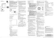
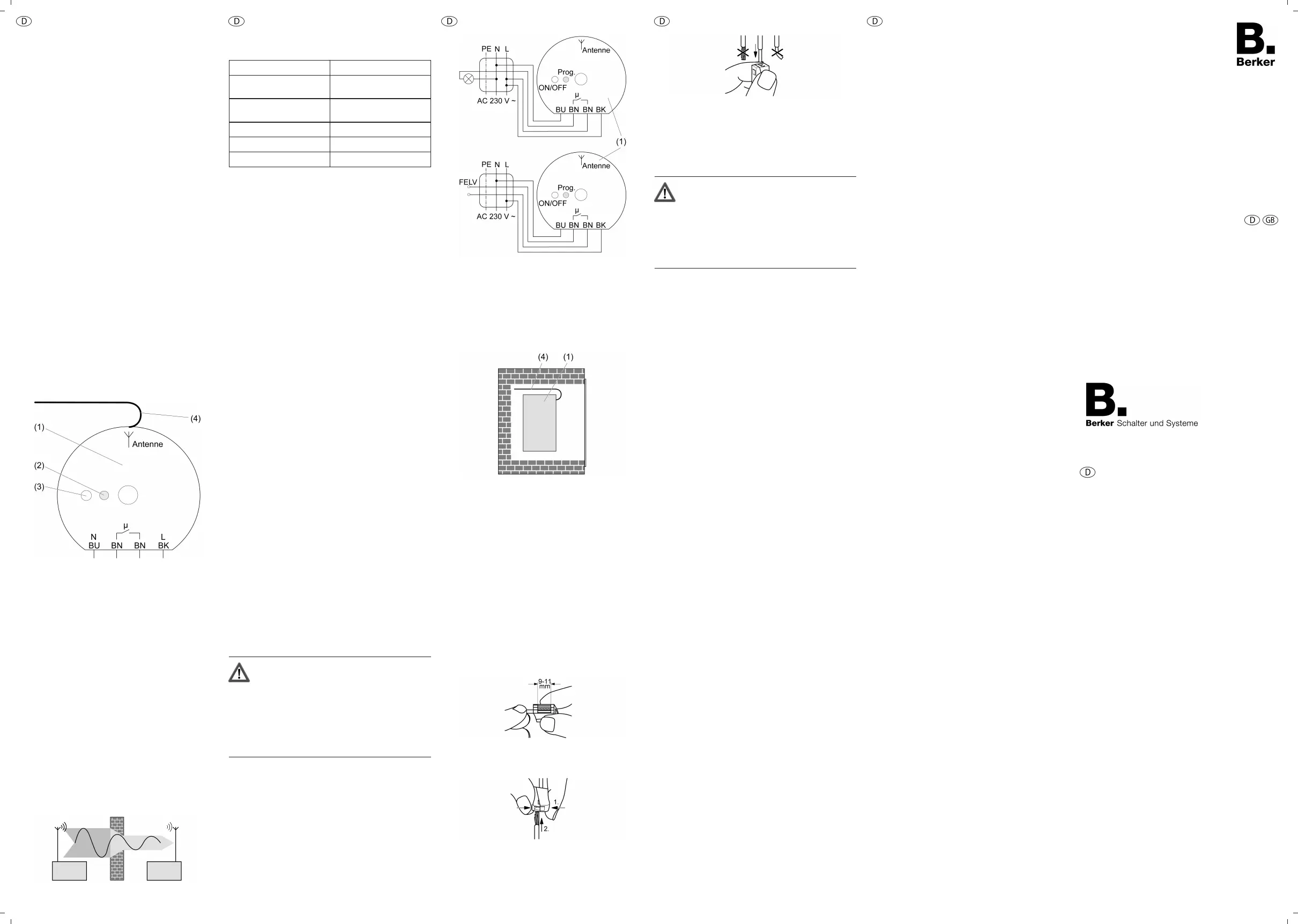
Bild 3
Blaue Leitung - BU, N, Neutralleiter
Schwarze Leitung - BK, L, AC 230 V~
Braune Leitungen - BN, µ, Schließerkontakt
o Schalt-/Tastaktor (1) gemäß Anschlussplan
(Bild 3) mit Leuchtenklemmen (siehe
Leuchtenklemmen verwenden) anschließen.
Bild 4
o Schalt-/Tastaktor so in die Gerätedose
einsetzen, dass die Programmiertaste und die
LED sichtbar sind.
i Antenne möglichst frei gestreckt verlegen
(Bild 4).
i Bei Montage außerhalb der Gerätedose, z. B.
Leuchten-Baldachin, auf ausreichende
Berührungssicherheit achten.
o Inbetriebnahme durchführen (siehe Kapitel
Inbetriebnahme).
o Blindabdeckung aufschrauben.
o Netzspannung einschalten.
i Durch kurzes Betätigen der Programmiertaste,
ca. 1 Sekunde, kann die Last ein- oder
ausgeschaltet werden.
Leuchtenklemmen verwenden
Bild 5: Abisolierlänge
o Leiter 9 - 11 mm abisolieren (Bild 5).
Bild 6: Anschluss des feindrahtigen Leiters
o Klemme auf der Seite mit der eckigen Öffnung
zusammendrücken und feindrahtigen Leiter
anschließen (Bild 6).
Bild 7: Anschluss des eindrahtigen Leiters
o Eindrahtigen Leiter bis zum Anschlag in eine
runde Öffnung auf der Installationsseite
hineinstecken (Bild 7).
Inbetriebnahme
GEFAHR!
Elektrischer Schlag beim Berühren
spannungsführender Teile.
Elektrischer Schlag kann zum Tod
führen.
Vor Arbeiten am Gerät
spannungsführende Teile in der
Umgebung abdecken!
i Anleitung des Funksenders beachten.
Funksender einlernen
i Sind alle Speicherplätze belegt, muss erst ein
bereits eingelernter Funksender gelöscht
werden. Dazu alle eingelernten Kanäle und
Lichtszenen des Funksenders einzeln löschen.
Abstand zwischen Empfänger und Funksender
beträgt 0,5 m bis 5 m.
Last ist ausgeschaltet.
o Programmiertaste ca. 4 Sekunden drücken.
LED blinkt. Last wird für 4 Sekunden
eingeschaltet, danach befindet sich der Schalt-/
Tastaktor für ca. 1 Minute im
Programmiermodus.
o Lerntelegramm am Funksender auslösen (siehe
Anleitung Funksender).
LED leuchtet. Funksender ist eingelernt.
o Programmmiertaste kurz drücken.
Last schaltet ein. Gerät befindet sich im
Betriebsmodus.
i Der Programmiermodus wird nach ca. 1 Minute
automatisch verlassen.
i Nur bei Schaltaktor: Lichtszenentasten separat
einlernen.
i Nur bei Schaltaktor: Beim Lernen eines
Funksenders werden eine vorhandene Alles-
Ein-Taste und Alles-Aus-Taste automatisch
mitgelernt.
Funksender einzeln löschen
o Zu löschenden Funksender erneut einlernen
(siehe Funksender einlernen).
LED blinkt schnell. Funksender ist gelöscht.
i Sind mehrere Kanäle oder Lichtszenen eines
Funksenders eingelernt, müssen alle einzeln
gelöscht werden.
Anhang
Technische Daten
Nennspannung AC 230 V ~
Netzfrequenz 50 / 60 Hz
Umgebungstemperatur -20 ... +55 °C
Relative Feuchte ca. 0 ... 65 % (keine
Betauung)
Leitungsschutzschalter max. 10 A
Anschlussleistung
i Leistungsangaben einschließlich
Trafoverlustleistung.
i Induktive Trafos mit mindestens 85 % Nennlast
betreiben.
Glühlampen 1000 W
HV-Halogenlampen 1000 W
Tronic-Trafos 750 W
Induktive Trafos 750 VA
Leuchtstofflampen
unkompensiert
500 VA
Leuchtstofflampen
parallelkompensiert
400 VA (47 µF)
Leuchtstofflampen Duo-
Schaltung
1000 VA
Schaltstrom bei AC 230 V ~
Ohmsch 8 A
Kontaktart µ-Kontakt, potentialfreier
Schließer
Anschluss
eindrähtig 1 ... 2,5 mm²
Abmessung Ø×H 52×23 mm
Ø Mittelloch 7,5 mm
Trägerfrequenz 433,42 MHz (ASK)
Einlernbare Funksender max. 14
Hilfe im Problemfall
Gerät reagiert nicht oder nur manchmal.
Ursache 1: Batterie im Funksender ist leer.
Batterie im Funksender wechseln.
Ursache 2: Funkreichweite überschritten. Bauliche
Hindernisse reduzieren die Reichweite.
Einbausituation prüfen.
Verlegung der Antenne prüfen. Gestreckte
Verlegung erhöht die Reichweite.
Einsatz eines Funk-Repeaters.
Zubehör
Der Tastaktor arbeitet nicht mit einem Funk-Sender
Up (Best.Nr. 0124) zusammen.
Gewährleistung
Technische und formale Änderungen am Produkt,
soweit sie dem technischen Fortschritt dienen,
behalten wir uns vor.
Wir leisten Gewähr im Rahmen der gesetzlichen
Bestimmungen.
Im Gewährleistungsfall bitte an die Verkaufsstelle
wenden oder das Gerät portofrei mit
Fehlerbeschreibung an unser Service-Center
senden.
Berker GmbH & Co. KG
Service-Center
Hubertusstraße 17
D-57482 Wenden-Ottfingen
Telefon: 0 23 55 / 90 5-0
Telefax: 0 23 55 / 90 5-111
Funkbus
09.05.2012
82532051
97-09513-000
Funk Schaltaktor 1fach UP, Funk
Tastaktor UP
Radio switch actuator, radio push-
button actuator - flush-mounted
Best.-Nr. /Order-No.
179, 179 50
Berker GmbH & Co. KG
Klagebach 38
58579 Schalksmühle/Germany
Telefon + 49 (0) 2355/905-0
Telefax + 49 (0) 2355/905-111
www.berker.de
Bedienungs- und
Montageanleitung
Operation- and
Assembly Instructions