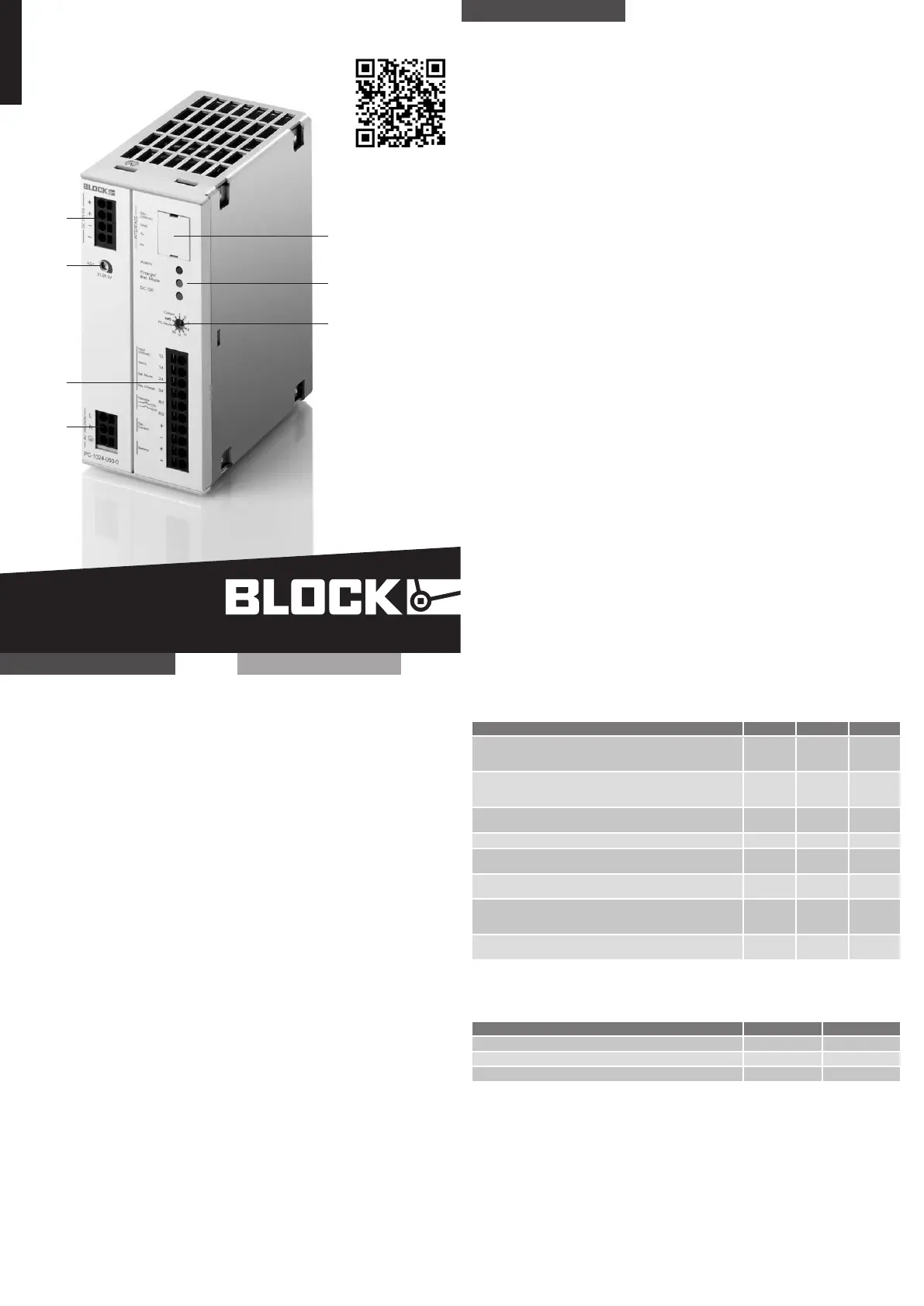
Safety measures before installation
This equipment is to be protected against improper use. Always disconnect the equip-
ment from the mains supply, before commencing installation or wiring.
Installation
Installation and commissioning may be carried out by qualified personal only. National
rules and regulations (e.g. VDE, DIN, EMC) have to be observed. The required minimum
spacing to neighboring components must be observed
to guarantee the required cooling.
To avoid faulty signalisations, the battery module should be connected com-
pletely before applying power to the device. For fault free operation the contacts
R1/R2 for the remote shot down should be shortened by a bridge or an (emergency)
switch.
The charge and control unit will detect the battery module automatically, if both con-
trol lines are connected (Battery Control). The device will adjust the optimal charge-
voltage and charge-current to provide optimal operation conditions for the battery.
It is recommended to connect the control lines for an optimal battery manage-
ment. Observe the correct polarity!
If several batteries are connected in parallel, the both control lines should be connec-
ted to only one of the batteries.
In order to guarantee effective cooling, the unit must be vertically installed such. To
reduce EMI and thermal strain DC-UPS modules and their battery modules should be
installed at least 50cm away from commutating chokes! Interface, signal and control
leads (e.g. R1/R2 and C+/C- control circuit) must be no longer than 3 meters and
must not be laid directly in parallel to power leads or cables (especially leads between
frequency converter and motor or frequency converter and commutating choke). DC
power leads are not allowed to exceed 10 m. To minimize EMI the distance to those
leads should be at least 10 cm. Battery modules should be connected low-resistively
and in a cool place (in cubicles usually at the lower end).
Read this first
Signaling
Descipsion LED green LED yellow LED red
UPS is operating in mains mode,
Output voltage > 20.4 V
Battery is charged and OK
on off off
UPS is operating in mains mode,
Battery is charging
(charge < 85% of nominal capacity)
on on off
UPS is operating in mains mode, no batter y mode is possible
(Battery presence check is failed or remote R1/R2 active)
on onoff
UPS is operating in mains mode, battery replacement is recommended on off Flashing (2Hz)
UPS is operating in buffer mode,
battery voltage > 20.4 V
on Flashing (2Hz) off
UPS is operating in buf fer mode,
battery voltage <= 20.4 V
on Flashing (8Hz) off
UPS protection against total discharge has terminated battery
Mode (Battery voltage <= 19.2 V)
continues indication for a maximum of 10 hours
off off Flashing (2Hz)
UPS is operating in buffer mode,
DC Output is switched off due to over current
off X Flashing (2Hz)
Notice: An individual assignment of the LED indicators is not possible.
LED
Signal outputs
State (def ault setting) Signal output Function
no battery mode is possible or battery replacement is recommended Alarm 13/14 active low (0 V)
UPS is operating in buf fer mode Bat. Mode 13/24 active high (24 V)
Battery is charging (charge < 85% of nominal capacity) Bat. Charge 13/34 active high (24 V)
Notice: The signal outputs can be parameterized individually using a service PC and the
UPS-CONTROL configuration and management software.
Anschluss
Eingang (7):
Zum Geräteschutz ist eine interne
Sicherung vorhanden. Ein zusätzlicher
Geräteschutz ist nicht erforderlich. Für
den Betrieb an zwei Außenleitern eines
Drehstromsystems muss eine allpolige
Trennvorrichtung vorgesehen werden.
Ausgang (1):
Die eingestellte Ausgangsspannung be-
trägt bei Auslieferung 24 V DC ±1%. Am
Potentiometer (3) ist die Ausgangsspan-
nung von 23 bis 28,5 V DC einstellbar. Bei
Ausfall der Versorgungsspannung wird
der Ausgang vom Batteriemodul gespeist.
Batteriemodul (6):
Der Anschluss erfolgt über die An-
schlussklemmen „Battery +/-“. Um die
intelligente Technology „Battery Control“
zu nutzen, müssen Sie zudem beide
Steuerleitungen (Bat.- Control +/-) für
die Kommunikation zwischen USV und
Batteriemodul installieren.
ACHTUNG: Für die Dauer der Installa-
tion oder Wechsel des Batteriemoduls
muss die Sicherung am Batteriemodul
ent fernt werden!
Signalausgänge (6):
Der Anschluss erfolgt über die Klemmen
“Alarm”, “Bat.-Mode” und “Bat.-Charge”. Al-
le drei Ausgänge besitzen einen gemeinsa-
men potenzialfreien und strombegrenzen-
den Sammeleingang, der über die Klemme
“Input” versorgt werden muss.
Fernabschaltung (6):
Soll die angeschlossene Last am Ausgang
des Kombi-USV-Moduls während des
Batteriebetriebs nicht aus dem Batte-
riemodul versorgt werden, z.B. im NOT
AUS Betrieb, kann der Batteriebetrieb
außer Funktion gesetzt werden. Hierzu
ist die Verbindung zwischen R1/R2 zu
unterbrechen.
Connection
Input (7):
An internal fuse is provided for device
protection. Additional device protection
is not required. For operation using two
phase conductors of a three-phase
system, an all-pole disconnecting device
must be provided.
Output (1):
The output voltage set upon delivery is
24 V DC ±1%. The output voltage can be
set from 23 V DC to 28.5 V DC on the
potentiometer (3). The output is supplied
by the battery if the supply voltage fails.
Battery module (6):
Connection of the battery module takes
place via the connection terminal block
„Battery +/-“. To make use of intelligent
technology “Battery Control”, you must
also install both control lines for the
communication between the UPS and
battery module.
ATTENTION: The fuse for the rechar-
geable battery module must be removed
when installing or replacing the module!
Signal outputs (6):
The signal outputs are connected via the
„Alarm“, „Bat.-Mode“, and „Bat.-Charge“
terminal blocks. All three outputs are
equipped with a common potential free
and short circuit proof sum-input, which
has to supplied via the terminal “Input”.
Remote shutdown (6):
If the connected load should not be sup-
plied from the buffer module in the event
that the AC voltage fails, the UPS can
be disabled via R1/R2. For a shutdown
the connection between R1/R2 must be
interrupted.
Funktionsweise
Ausgangsspannung (1):
Im Normalbetrieb beträgt die Ausgangs-
spannung der Einstellung des Potentio-
meters (3). Bei Ausfall der Versorgungs-
spannung wird unterbrechungsfrei auf
den Batteriebetrieb umgeschaltet . Die
Ausgangsspannung ist jetzt direkt von
der Batteriespannung abhängig und
beträgt UBAT - 0,5V.
Einstellung der Pufferzeit (5):
Die Einstellung der Zeit, die den Bat-
teriebetrieb beendet, erfolgt über den
Wahlschalter (5) auf der Gerätefront.
Dabei kann zwischen festen Zeiten,
einer individuell programmierbaren Zeit
oder der Einstellung „PC-Mode“ gewählt
werden.
PC-Mode:
In dieser Einstellung folgt die Kombi-
USV einer paramet rierbaren zeitlichen
Abfolge von „Verzögerungszeit“ (default:
60 Sek.), „PC-Herunterfahren“ (default:
120 Sek.) und „PC-Leerlaufzeit“ (default:
10 Sek.). Wahlweise kann ein beliebiger
Signalausgang für das Herunterfahren
des PCs konfiguriert werden. Hierzu ist
eine individuelle Parametrierung über
die kostenlose Konfigurations- und
Managementsoft ware „USV-CONTROL“
erforderlich.
Interface (2):
Das Modul kann mit einem PC oder einer
übergeordneten Steuerung kommunizie-
ren. Durch das halbsekündliche Aussen-
den aller Eckdaten ist es möglich, neben
der Visualisierung relevant er Daten,
auch auf kritische Betriebszustände zu
reagieren. Eine Parametrisierung kann
ebenfalls über diese Schnittstelle erfol-
gen. Um die Schnittstelle direkt nutzen
zu können, ist das Kommunikationskabel
PC-KOK1 optional erhältlich
Method of Operation
Output voltage (1):
In normal operation (mains mode) the
output voltage corresponds to the
setting on the Potentiometers (3). If
the supply voltage fails, battery mode is
activated without any interruption. The
output voltage is now directly dependent
on the battery voltage and is UBAT - 0,5V.
Buffer time setting (5):
The time setting for shut down the
battery mode can be set via the selector
switch (5) on the front of the device. It
can be chosen between predefined times,
a individual parametrable time or the
setting „PC-Mode“.
PC-Mode:
In „PC mode“, the UPS function follows
a chronological sequence „PC delay
time“ (default: 60 sec.), „PC-shut down“
(default: 120 sec.) und „PC-idle time“
(default: 10 sec.)that can be paramete-
rized via the software and individually
optimized for the relevant IPC solution.
It performs a controlled shutdown and
restart automatically. A signal output
to shutdown the PC can be set via con-
figurations- and management software
„UPS-CONTROL“.
Interface (2):
The interface enables the device to
communicate with a PC or a PLC. The
device sends key data every 0.5 seconds,
enabling the visualisation of the data or
the reaction on critical operational condi-
tions. The device may also be configured
via the interface. For direct use of the
interface, the optional communication
cable PC-KOK1 is available.