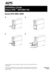
Sicherheitsmaßnahmen vor der Installation
Das Betriebsmittel ist vor unzulässiger Beanspruchung zu schützen.
Insbesondere dürfen bei Transport und Handhabung keine Bauele-
mente verbogen und/oder Isolationsabstände verändert werden. Die
Berührung elektrischer Bauelemente und Kontakte ist zu vermeiden.
Betriebsmittel immer im spannungsfreien Zustand montieren und
verdrahten. Die Produktbeschreibung und die technischen Hinweise in
unserem Hauptkatalog sowie die Aufschriften am Betriebsmittel und
auf dem Typenschild sind zu beachten.
Die Installation ist entsprechend den örtlichen Gegebenheiten,
einschlägigen Vorschriften (z. B. VDE 0100), nationalen Unfallverhü-
tungsvorschriften (z. B. UVV-VBG4 bzw. BGV A2) und den anerkannten
Regeln der Technik durchzuführen. Dieses elektrische Betriebsmittel
ist eine Komponente, die zum Einbau in elektrische Anlagen oder
Maschinen bestimmt ist und erfüllt die Anforderungen der Niederspan-
nungsrichtlinie (73/23/ EWG). Der geforderte Mindestabstand von
10 mm zu benachbarten Teilen ist unbedingt einzuhalten, um die Küh-
lung nicht zu behindern! Bei Einbau in Maschinen ist die Aufnahme des
bestimmungsgemäßen Betriebes solange untersagt, bis festgestellt
wurde, dass die Maschine den Bestimmungen der Maschinenrichtlinie
(89/392/EWG) entspricht; EN 60204 ist zu beachten. Die Aufnahme
des bestimmungsgemäßen Betriebes ist nur bei Einhaltung der EMV-
Richtlinie (89/336/EWG) erlaubt. Die Einhaltung der durch die EMV-
Gesetzgebung geforderten Grenzwerte liegt in der Verantwortung des
Herstellers der Anlage oder Maschine.
BLOCK Transformatoren-Elektronik GmbH & Co. KG
Technische Änderungen vorbehalten.
KAPVUA 06.07.PDF.0 Printed in Germany ©G.V.K. 3rd unit Lüneburg
Unterbrechungsfreie Stromversorgung
Uninteruptable power supply
LEDs: Die grüne LED (a) leuchtet, wenn kein Fehler vorliegt. Die
gelbe LED (b) zeigt Warnungen an. Die gelbe LED (b) blinkt bei
Pufferbetrieb im 0,4 Sek.-Takt. Die gelbe LED (b) blinkt bei geringer
Batteriespannung im Pufferbetrieb im 0,2 Sek.-Takt. Die rote LED
Display der Kontrolleinheit: Das Parametrisieren über das
Display wird rückseitig erklärt.
Tasten: Linke Taste = vorwärts im Menü, rechte Taste =
Signale: siehe Anschlussplan rückseitig
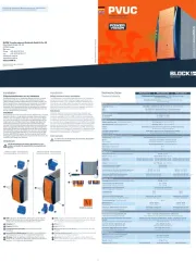
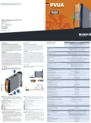
Montage: PVUA mit geöffneter Schließnocke (8a) im rechten
Winkel auf die Tragschiene TS35 setzen. Befestigung mit Schrau-
bendreher im Uhrzeigersinn schließen(8b).
Schnittstelle und Signalausgänge
: Die Schutzkappe ist zur
Vermeidung statischer Entladungen nur unter Anwendung von
ESD-Schutzmaßnahmen abzunehmen.
1 Inaktiv bei Pufferbetrieb,
>10 A, 3 inaktiv bei Abschaltung durch Über-
Frei belegbare Ausgänge, konfigurierbar per PC mit
1 Verknüpfung mit potentialfreiem Wechselkon-
568 Kommunikationsein- und Ausgänge,
Die Schnittstelle ist nicht galvanisch getrennt. Ein geeignetes
Adapterkabel (PV-KOK2) oder den passenden Stecker (PV-CON)
können Sie über BLOCK beziehen. Bei Anschluß eines Relais an
einen Signalausgang muß zwingend eine Freilaufdiode vorhanden
Download der ausfühlichen Betriebsanleitung unter: www.pv400.de
Download the complete user manual at www.pv400.de
Unterbrechungsfreie Stromversorgung
für TS35-Schienenmontage oder Schraubbesfestigung
Uninterruptible power supply
for mounting on DIN 35mm rails or screw mounting.
Sicherheit Safety EN 60950, UL 60950, UL 508 EN 60950, UL 60950, UL 508
EN 61000-6-2 und EN 61000-6-3 (Fachgrundnormen)
EN 61000-6-2 and EN 61000-6-3 (generic standard)
UL (vorbereitet) UL (Pending) UL 60950 (CSA C22.2/No.60950) UL 60950 (CSA C22.2/No.60950)
UL (vorbereitet) UL (Pending) UL 508 (CSA C22.2/No.14-95) UL 508 (CSA C22.2/No.14-95)
Umgebungstemperatur Ambient temperature –10° C bis +60° C –10° C to +60° C
Lagertemperatur –25° C bis +85° C Storage –25° C to +85° C
Selbstkühlung durch natürliche Konvektion bei vertikaler Einbaulage
AN (Natural air convection cooling)
Zulässige Luftfeuchtigkeit
30 bis 85% relative Feuchte, keine Betauung zulässig
30 to 85% relative humidity with no dew
Sicherheit und Schutz Safety and protection
Prüfspannung HV test voltage
500 Vdc (Klemmen zum Gehäuse) 500 Vdc (terminals to enclosure)
gekapselt, für den Einbau im Schaltschrank
enclosed for installation in switching cabinets
Schutzart IP 20 (nach EN 60529) Protection index IP 20 (to EN 60529)
Schutzklasse Safety class III III
Eingangsnennspannung Designated input voltage 24 Vdc 24 Vdc
Bereich Voltage range 20,4 Vdc bis 28,8 Vdc 20,4 Vdc to 28,8 Vdc
Zuschaltschwelle (einstellbar)
Threshold level (adjustable)
Pufferzeit (einstellbar) Puffer time (adjustable) 10 Sek. bis 10 Min. / dauerhaft 10 sec. to 10 min. / constant
Eingangssicherung Input fuse rating intern 15 A internal 15 A
Einschaltstrom ohne Last In-rush current no load typ. 4 A typ. 4 A
Stromaufnahme (Leerlauf/Ladevorgang/max)
Input current (no load/charging process/max.)
Ausgang Nennbetrieb Output normal operation
Nennausgangsspannung Designated output voltage 24 Vdc 24 Vdc
Ausgangsspannung Output voltage
Ausgangsstrom Output current
Strombegrenzung mit Abschaltung
Current limitation with power off
Überlastsicherung Overload fuse rating intern 15 A internal 15 A
Ausgang Pufferbetrieb Output puffer operation
Nennausgangsspannung Designated output voltage 24 Vdc 24 Vdc
Ausgangsspannung (einstellbar)
Output voltage (adjustable)
Ausgangsstrom Output current 10 A 10 A
Strombegrenzung mit Abschaltung
Current limitation with power off
Überlastsicherung Overload fuse rating intern 15 A internal 15 A
Fernabschaltung Remote power off ja yes
Ladekennlinie Charging characteristic siehe Kennlinie see characteristic curve
Ladeschlussspannung (einstellbar oder temperatur-
geführt) Charging voltage upper level (adjustable or
26 bis 29,5 Vdc oder laut Kennlinie
26 to 29,5 Vdc or according to characteristic curve
Ladestrom Charging current 0,2A/0,4A/0,6 A 0,2A/0,4A/0,6 A
Temperaturkompensation Temperature compensation ja yes
Accumulator presence self check
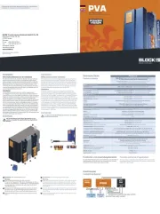
Speichermedium (empfohlen: PVA 24/3,2 Ah) Storage medium (recommended: PVA 24/3,2Ah)
Nennspannung Designated voltage 24 Vdc 24 Vdc
Nennkapazität Designated capacity 3,2 Ah 3,2 Ah
Lebensdauer Life expectancy laut Herstellerangabe according to manufacturer specifications
Anschlüsse: WAGO Multisteckersystem
Terminals: WAGO multi plug system
WAGO Serie 231, max 2,5 mm², WAGO Serie 733, max 0,5 mm²
WAGO series 231, max 2,5 mm², WAGO series 733, max 0,5 mm²
Tragschienenmontage (DIN EN 60715:2001-09) mit zwei
Montagemöglichkeiten oder Direktverschraubung
rail mounting (DIN EN 60715:2001-09) with two possible varieties
Verpackung Packing Einzelverpackung im Karton single packed in carton
Maße B x H x T (ohne Anschlussstecker)
Dimensions width x height x depth
Gewicht Weight 0,8 kg 0,8 kg
www.pv400.de
KAPVUA 2007•06
Safety measures before installation
This equipment is to be protected against improper use. Components
are not to be bent or isolation spacing changed, especially through
handling and transport. The contact with electrical components and
terminals is to be avoided. Always disconnect the equipment from the
mains supply, before commencing installation or wiring. The product
description, technical information in our main catalogue and the mar-
king on the equipment ratings plate are to be observed.
Installation must be carried out according to the prevailing local
conditions and safety regulations (e.g. VDE 0100) national accident
prevention regulations (e.g. UVV-VBG4 or BGV A2) and the generally
accepted rules of technology. This equipment is a component designed
for installation into electrical systems and machines, and fulfils the
requirements of the low voltage guidelines (73/23/EWG). The required
min spacing of 10 mm to neighbouring components must be observed
to guarantee the required cooling. When installed into machinery, the
normal operation is forbidden until it is determined that the machine
fulfils the requirements of the machinery guidelines (89/392/EWG).
EN 60204 must be observed. The EMC requirements must be fulfilled
before operation is commenced. The observance of the required limita-
tions for the EMC legislation is the responsibility of the manufacturer of
the installation or machinery.
To reduce the risk of mistaking the terminals, the supplied
Um Verwechslungen mit anderen Anschlüssen zu ver-
meiden, verwenden Sie ausschließlich die mitgelieferten
LEDs: The green LED (a) lights for normal operation. The yellow
LED (b) shows a warning. The yellow LED (b) blinks in 0,4 sec. cycle,
indicating puffer operation. The yellow LED (b) blinks when the
battery voltage is low in puffer operation at 0,2 sec. cycle. The red
LED (c) indicates a fault condition.
The control unit display: The parameter adjustments are descri-
bed on the back of this leaflet.
Buttons: Left button = forwards in the menu, right button = to
alter parameter settings.
ACC: accumulator terminals
Signals: see connection plan on the reverse side
Mounting: Place the PVUA with opened cam lock (8a) in a 90°
angle on the DIN 35 mm rail and close the cam lock in a clockwise
direction with a screwdriver (8b).
Interface and signal ports
: The protective cap is to reduce the
risk of static discharge and should only be removed with the use
of ESD protective measures
1 Inactive during puffer operation,
>10 A, 3 Inactive if overload protection has
free output connections that can be configured per
1 link to a potential free switch, 568
communication in and output, 7 output voltage.
The interface has no galvanic separation and should only be
connected with a suitable adapter cable (PV-KOK2) or the plug (PV-
CON) that are available from Block. If a relay is to be connected to a
signal output then it is imperative that a free running diode be used.