Bobrick B-878 Manual
Bobrick
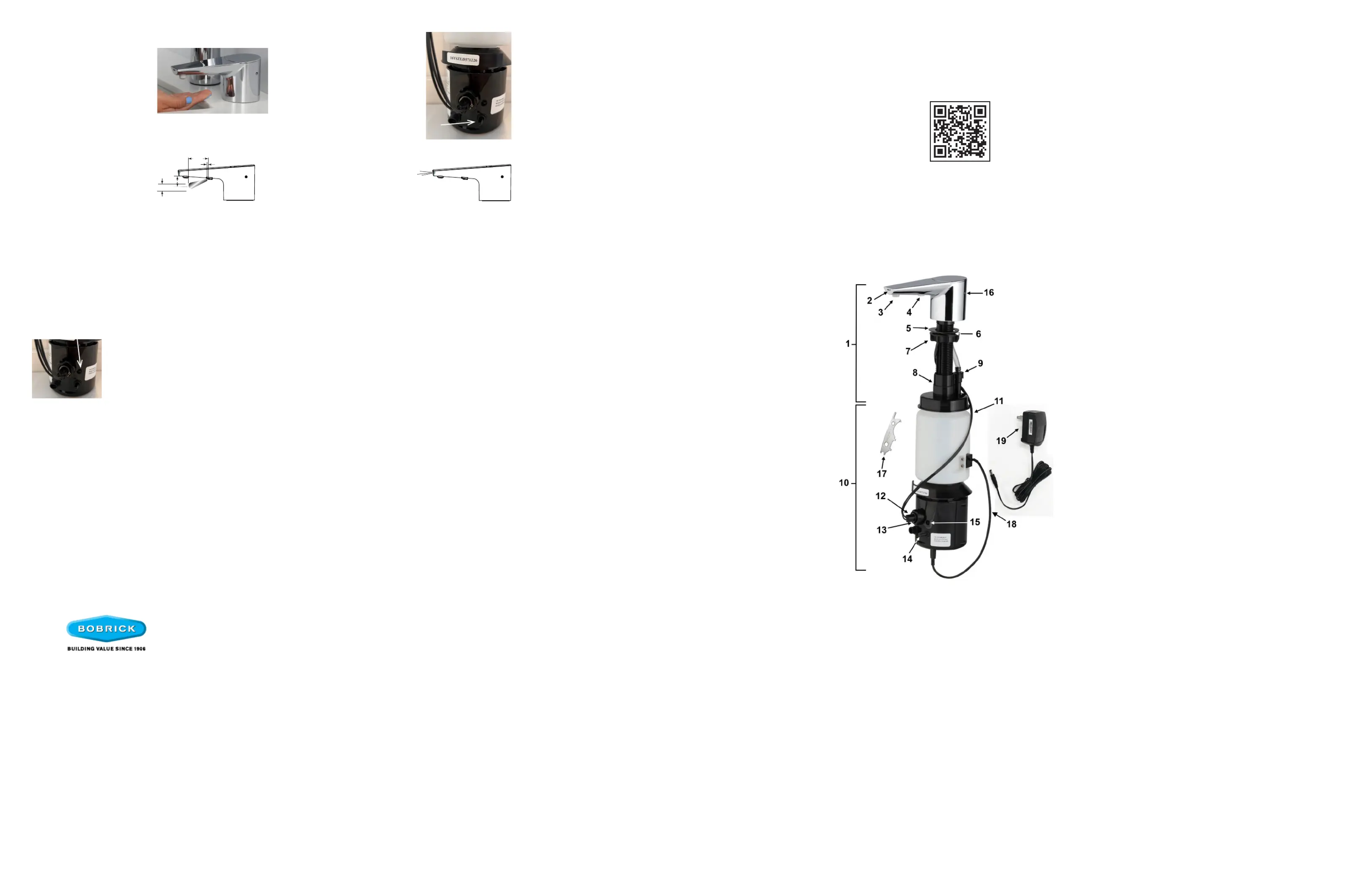
Sæbedispenser
B-878
| Mærke: | Bobrick |
| Kategori: | Sæbedispenser |
| Model: | B-878 |
Har du brug for hjælp?
Hvis du har brug for hjælp til Bobrick B-878 stil et spørgsmål nedenfor, og andre brugere vil svare dig
Sæbedispenser Bobrick Manualer

19 November 2025

18 November 2025
20 August 2025

22 Juni 2025
16 Juni 2025

15 Juni 2025
15 Juni 2025

15 Juni 2025
15 Juni 2025
Sæbedispenser Manualer
- Ikea
- SilverCrest
- Bartscher
- Tork
- Basetech
- ECG
- Teesa
- Elkay
- Purell
- Sloan
- Bradley
- Lavex
- Simplehuman
- Waterloo
Nyeste Sæbedispenser Manualer
9 Oktober 2025
2 Oktober 2025
29 September 2025

29 September 2025
26 September 2025
17 September 2025
29 August 2025

29 August 2025
28 August 2025
28 August 2025