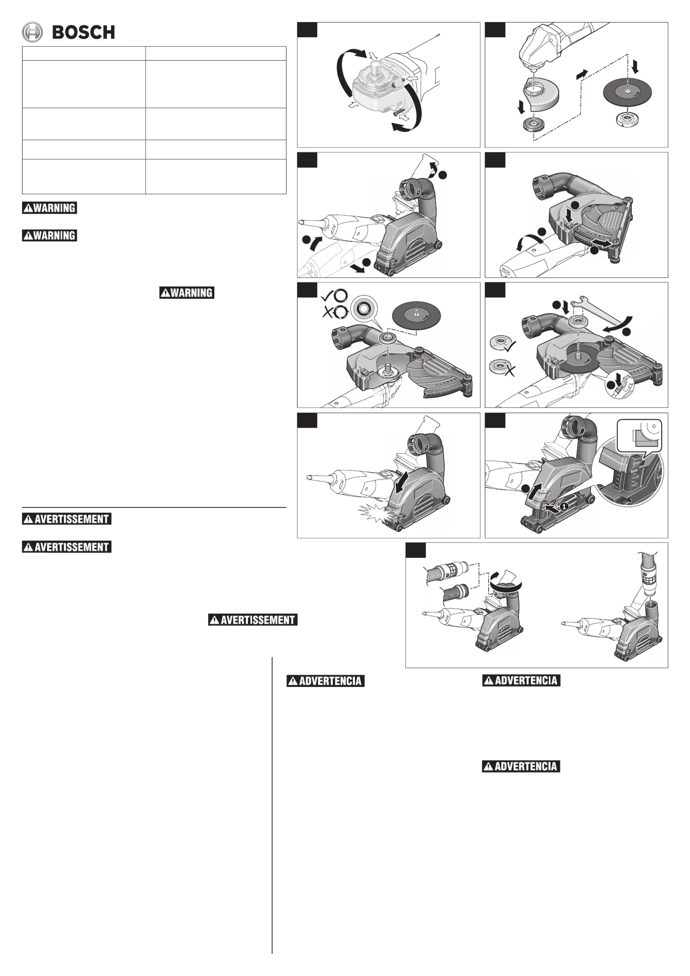
DUST COLLECTION GUARD INSTALLATION
•Disconnect tool from power source. Remove
Guard: Depress release button, rotate guard
until arrow on guard lines up with arrow on
spindleneck,andremoveguardfromspindle
neck.Removesidehandle(Fig.B).
•Positiongrinderandguardinthesamefashion
asinFig.C,startingthegrinderinposition .➊
Alignthearrowonthegrinderwiththeclosest,
visibledetent ontheguard. Turntheguard 5
degreestowardyou,untilthehandlebracketis
restingonthegrinder,centeredoverthethread-
edholethatreceivesthathandle.Reinstallthe
accessory handleinto thishole to securethe
•Turnthegrinderonitsside .Depressredbut➊-
ton andholdwhilepullingthebottomhalfof➋
theguard completelyfreeofthetophalfof➌
•Align backing flange on spindle, followed by
thecuttingwheel.Makesurethatthebacking
flangeis properly seatedand that thecutting
wheelissituatedinthecorrectcuttingdirection
•Oncethebackingflangeandcuttingwheelare
correctly placed, install the clamping flange.
Handtightensothattheflangeissnugagainst
the wheel. Then, depress the spindle lock ➋
andholditwhiletighteningtheclampingflange
withaBoschSpannerwrench(Fig.F).
•Closethecuttingguardbydepressingthered
buttonandslidingtheupperguardintothebot-
tomguarduntiltheguardiscompletelyclosed
• Oncetheguardhasbeencompletelyshutyoumay
nowselectthedepthofcutyouwishtomake.All
measurementsareinmillimeters(Fig.H).
•Attachthevacuumhosetoeitherthe360de-
greeswivelattachmentordirectlytotheguard
itself.Thiswillvarybyapplication(Fig.I).
ConcreteCutOffDustCollectionGuard
Dispositif de protection du système de dépous-
siéragepourlacoupedebéton
Protectorderecoleccióndepolvoproducidoalcor-
Type41/1AMasonryCutting
Outildecoupedemaçonneriedetype41/1A
Cortedemamposteríatipo41/1A
Diameters Accepted / Diamètres acceptés /
Compatibleaveclesmodèlesdemeuleuses
Funcionaenlosmodelosdeamoladora
1800,1801,1803EVS,1810PS,1810PSD,1811PS,
1811PSD,1821,1821D,AG40-11PD,AG40-11P,
AG40-85,AG40-85PD,AG40-85P,AG50-10,
AG50-11VS,AG50-11VSPD,AG50-125PD
Read the tool manual and these instructions for the use of this accessory with
USE ONLY TYPE 41/1A MASONRY CUTTING WHEELS
Wheel guard must be attached when using type 41/1A cutting wheels. Use
only with type 41/1A cutting wheels. Always keep guard between you and
your work while cutting. Wear eye, dust and ear protection. Always use side handle.
1-877-BOSCH99 (1-877-267-2499)
TOOL PREPARATION (Fig. A)
Disconnectplugfrompowersource.Completely
unscrewthefourscrewsandrotatethetoolhead
carefully to the new position without removing
it from the housing. For paddle switch tools,
switch should face “down” towards work sur-
face. For slide switch tools, slide should face
“up”towardsuser,sothe toolcanbeused for
longmasonrycuttingapplications.Screwinand
tightenthefourscrewsagain.
Return tool head to origi-
nal position when return-
ing to grinding, sanding, brushing or metal cut-
INSTALLATION DU DISPOSITIF DE PROTECTION
DU SYSTÈME DE DÉPOUSSIÉRAGE
•Débranchez votre outil de sa source
d’alimentation électrique. Retraitdu dis-
positif de protection : Appuyez sur le
boutonderelâchement, faitestournerle
dispositifdeprotectionjusqu’àcequela
flèchesurledispositifdeprotectionsoit
alignéesurlaflècheducoldel’arbre,puis
retirezledispositifdeprotectionducolde
l’arbre.Retirezlapoignéelatérale(Fig.B).
•Positionnezlameuleuseetledispositifde
protectiondelamêmemanièrequesurle
Fig.C,encommençantaveclameuleuse
danslaposition .Alignezlaflèchesurla➊
meuleusesurlecranvisibleleplusproche
dudispositifdeprotection.Faitestourner
le dispositif de protection de 5 degrés
versvous, jusqu’àce quele support de
lapoignéereposesurlameuleuse,centré
surletroufiletéquireçoitcettepoignée.
Réinstallezlapoignéeaccessoiredansce
trouafindesécuriserledispositifdepro-
tectiondu mécanismededépoussiérage
pourlacoupedebéton(Fig.C).
•Tournezlameuleusepourqu’ellerepose
sur son côté . Appuyez sur le bouton➊
rouge ettenez-leenfoncétoutentirant➋
sur la moitié inférieure du dispositif de
protection pourladétachercomplète➌-
mentdelamoitiésupérieuredudispositif
•Alignezlaflasquedesupportsurl’arbre,
puisfaitesdemêmepourlameule.Veillez
àcequelaflasquedesupportreposecor-
rectementàl’endroitprévuàceteffetet
quelameulesoitsituéedanslesensde
•Après que la flasque de support et la
meule auront été placées aux endroits
appropriés,installez la bride defixation.
Serrezàlamaindetellesortequelabride
repose naturellement contre la meule.
Puis appuyez sur le mécanisme de ver-
rouillage de l’arbre et tenez-le dans➋
cettepositionpendantquevousserrezla
bridedefixationavecuneclétricoisede
•Fermezledispositifdeprotectiondel’outil
decoupeenappuyantsurleboutonrouge
etenfaisantglisserlapartiesupérieuredu
dispositifdeprotectiondansledispositif
deprotectiondubasjusqu’àcequeledis-
positif de protection soit complètement
•Après avoir fermé complètement le dis-
positifdeprotection,vouspouvezsélec-
tionner la profondeur de la coupe que
vousdésirezréaliser.Touteslesmesures
sontenmillimètres(Fig.H).
•Attachez le tuyau de l’aspirateur à
l’élément pivotant sur 360 degrés ou
directement au dispositif de protection
lui-même.Toutdépendradesbesoinsde
Lisez le mode d’emploi et ces instructions pour apprendre à uti-
liser cet accessoire avec votre outil.
UTILISEZ SEULEMENT DES MEULES À COUPER LA MAÇONNERIE DE TYPE 41/1A
Le dispositif de protection de la meule doit être attaché en cas
d’utilisation de meules de coupe de type 41/1A. Utilisez seulement
avec des meules de type 41/1A. Veillez à ce que le dispositif de protection de la meule soit toujours
placé entre votre ouvrage et vous pendant les opérations de coupe. Portez des verres protecteurs, des
bouche-oreilles et un masque contre les poussières. Utilisez toujours une poignée latérale.
PRÉPARATION DE L’OUTIL (Fig. A)
Débranchezlafichedelaprisedecourant.Dévissezcomplètement
lesquatrevis etfaitestourner latêtede l’outilenprenant toutes
lesprécautionsnécessairesjusquedanslanouvellepositionsans
lefairesortirdesonboîtier.Pourlesoutilsayantuncontacteurà
palette,lecontacteurdoitêtreorientéverslebas,endirectiondela
surfacedetravail.Pourlesoutilsayantuninterrupteurcoulissant,
l’interrupteurdoitêtreorientéversl’utilisateurdefaçonquel’outil
puisseêtreutilisédanslecadred’applicationsdecoupedemaçon-
neriedelonguedurée.Vissezetserrezlesquatrevisànouveau.
Remettez la tête de l’outil dans
la position originale lorsque
vous souhaitez l’utiliser à nouveau pour des applications de meu-
lage, de ponçage, de brossage ou de coupe de métal.
INSTALACIÓN DEL PROTECTOR DE RECOLECCIÓN DE POLVO
•Desconecte la herramienta de la fuente de
alimentación.Retireelprotector:Presioneel
botóndeliberación,roteel protectorhasta
quelaflechaubicadaenelmismosealinee
conlaflechaubicadaenelcuellodelhusillo
yretireelprotectordelcuellodelhusillo.Re-
tireelmangolateral(Fig.B).
•Posicionelaamoladorayelprotectordela
mismamaneraqueenelFig.C,ubicandola
amoladoraenlaposición1.Alineelaflecha
ubicadaenlaamoladoraconelreténvisible
máscercanodelprotector.Gireelprotector
5gradoshaciausted,hastaqueelsoporte
delmangoestédescansandosobrelaamo-
ladora, centrado sobre el agujero roscado
querecibe ese mango.Reinstale elmango
accesorioenesteagujeroparasujetarfirme-
menteelprotectordecorte(Fig.C).
•Volteelaamoladorasobreunodesuslados
➊ ➋.Presioneel botónrojo ymanténgalo
presionadomientrasjalalamitadinferiordel
protector hasta que se libere completa➌-
mentedelamitadsuperiordelprotector(Fig.
•Alineelapestañadesoportesobreelhusillo,
seguido por la rueda de corte. Asegúrese
dequelapestañadesoporteestéasentada
adecuadamenteyquelaruedadecorteesté
situadaenelsentidodecortecorrecto(Fig.
•Unavezquelapestañadesoporteylarueda
decorteesténcolocadascorrectamente,in-
stalelapestañadefijación.Aprieteamanola
pestañademaneraquequedeperfectamente
ajustadacontralarueda.Luego,presioneel
cierredelhusillo➋ymanténgalopresionado
mientrasaprietalapestañadesujecióncon
unallavedeganchoBosch(Fig.F).
•Cierre elprotector de cortepresionando el
botónrojoydeslizandoelprotectorsuperior
haciaelinteriordelprotectorinferior,hasta
queelprotectorestécompletamentecerrado
•Unavezquesehayacerradocompletamente
elprotector,ustedpodráseleccionarlapro-
fundidaddecortealaquedeseecortar.To-
daslasmedicionessonenmilímetros(Fig.
•Acople la manguera de aspiración ya sea
aladitamentogiratoriode360gradosodi-
rectamentealpropioprotector.Estovariará
Lea el manual de la herramienta y es-
tas instrucciones para el uso de este
accesorio con su herramienta.
UTILICE ÚNICAMENTE RUEDAS PARA CORTAR MAMPOSTERÍA TIPO
El protector de la rueda debe estar in-
stalado cuando se utilicen ruedas de
corte tipo 41/1A. Utilice únicamente ruedas de corte tipo 41/1A. Man-
tenga siempre el protector entre usted y la pieza de trabajo mientras
esté cortando. Use protección de los ojos, antipolvo y de los oídos.
Usar siempre el mango lateral.
PREPARACIÓN DE LA HERRAMIENTA (Fig. A)
Desconecteelenchufedelafuentedealimentación.Desenrosquecom-
pletamenteloscuatrotornillosyrotecuidadosamentelacabezadela
herramientahastalaposición nuevasinretirarlade lacarcasa.Enel
casodeherramientasconinterruptordepaleta,el interruptordeberá
estarorientadohacia“abajo”,hacialasuperficiedetrabajo.Enelcaso
deherramienta coninterruptordeslizante, elinterruptor deberáestar
orientadohacia“arriba”,haciaelusuario,paraquelaherramientase
puedautilizarparaaplicacionesprolongadasdecortedemampostería.
Enrosqueyaprietedenuevoloscuatrotornillos.
Devuelva la cabeza de la herramienta
a la posición original cuando regrese a
aplicaciones de amolado, lijado, cepillado o corte de metales.


