Broan 770RLTKC Manual
Broan
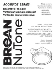
Ventilator
770RLTKC

| Mærke: | Broan |
| Kategori: | Ventilator |
| Model: | 770RLTKC |
Har du brug for hjælp?
Hvis du har brug for hjælp til Broan 770RLTKC stil et spørgsmål nedenfor, og andre brugere vil svare dig
Ventilator Broan Manualer
19 Oktober 2025
7 August 2025
8 Juli 2025

7 Juli 2025
7 Juli 2025
7 Juli 2025

7 Juli 2025
7 Juli 2025
7 Juli 2025
7 Juli 2025
Ventilator Manualer
- Proklima
- Ozito
- Heylo
- Tecnolux
- Magnavox
- Evolar
- SEPA
- Point
- Listo
- Klarstein
- Sandstrøm
- Bodin
- Canarm
- Hornbach
- RYOBI
Nyeste Ventilator Manualer
1 November 2025
1 November 2025
1 November 2025
1 November 2025

1 November 2025
1 November 2025
1 November 2025
1 November 2025
31 Oktober 2025
31 Oktober 2025