Canarm CEPD140-4 Manual
Canarm
Ikke kategoriseret
CEPD140-4

| Mærke: | Canarm |
| Kategori: | Ikke kategoriseret |
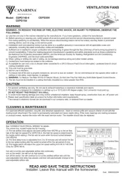
| Model: | CEPD140-4 |
Har du brug for hjælp?
Hvis du har brug for hjælp til Canarm CEPD140-4 stil et spørgsmål nedenfor, og andre brugere vil svare dig
Ikke kategoriseret Canarm Manualer

18 September 2025

17 September 2025
17 September 2025
17 September 2025
17 September 2025
17 September 2025
17 September 2025
17 September 2025
17 September 2025
16 September 2025
Ikke kategoriseret Manualer
- Artusi
- ROCWARE
- Barco
- GUS
- Aqprox
- Roesle
- Buzz Rack
- Salton
- Cadco
- Crew Dog Electronics
- Tycon Systems
- Sincreative
- Dream Mate
- Bauhn
- Aeon Labs
Nyeste Ikke kategoriseret Manualer

21 December 2025

21 December 2025

21 December 2025

21 December 2025

21 December 2025

21 December 2025

21 December 2025

21 December 2025

20 December 2025

20 December 2025