Manufacturer reserves the right to discontinue, or change at any time, specifications or designs without notice and without incurring obligations.
Catalog No. 04-53330023-01 Printed in U.S.A. Form 33CS-23SO Pg 1 8-11 Replaces: New
Part Number 33CSCNACHP-01
Read and follow manufacturer instructions carefully. Fol-
low all local electrical codes during installation. All wiring
must conform to local and national electrical codes. Improper
wiring or installation may damage thermostat.
Recognize safety information. This is the safety alert sym-
bol . When the safety alert symbol is present on equipment
or in the instruction manual, be alert to the potential for person-
Understand the signal words DANGER, WARNING, and
TION. These words are used with the safety alert symbol.
DANGER identifies the most serious hazards which will result
in severe personal injury or death. WARNING signifies a haz-
ard which could result in personal injury or death. CAUTION
identify unsafe practices which would result in minor
personal injury or property damage.
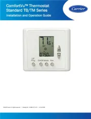
Carrier's Comfort Pro non-programmable thermostats are
wall-mounted, low-voltage thermostats which maintain space
temperature by controlling the operation of a heating and/or air
conditioning system. This thermostat can be used with a heat
pump, air conditioner or water source heat pump operation. A
variety of features are provided including battery operation,
separate heating and cooling set points, auto changeover, key-
pad lockout, and backlighting.
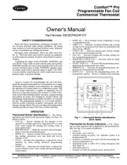
Thermostat Button Identification —
ing buttons are located on the thermostat display. See Fig. 1 for
• FAN (1) — Selects whether the
ously (on) or only when needed for heating or cooling
• MODE (2) — Selects whether thermostat is set for heat-
ing, cooling, emergency heat, auto (heat and cool as
• UP (3) — Increases the temperature or adjusts
selection up when setting advanced features
• DOWN (4) — Decreases the temperature
screen selection down when setting advanced features
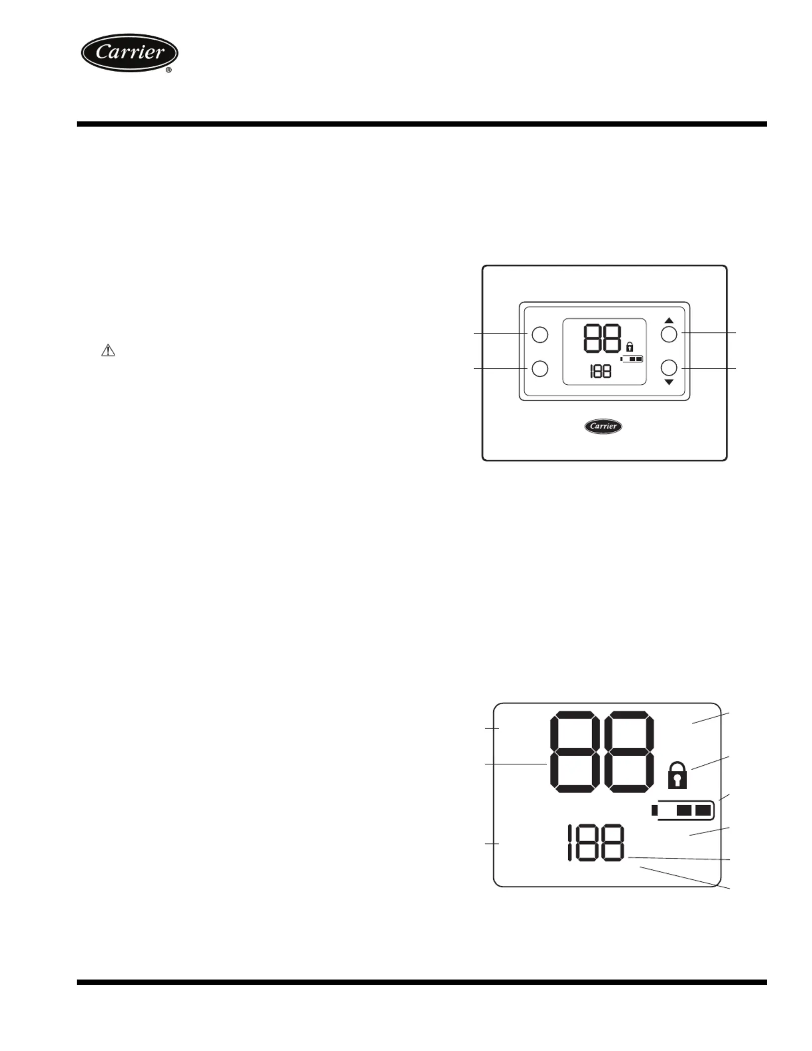
Thermostat On-Screen Indicators — The follow-
ing on-screen indicators can be displayed on the thermostat dis-
play. See Fig. 2 for location of indicators.
• Fan mode - on or auto (1)
• Current temperature (2)
• Fahrenheit or Celsius units (4)
• Keypad is locked (no padlock means unlocked) (5)
• Battery strength indicator (6)
• Second stage is active (cooling or heating if available)
Fig. 1 — Thermostat Button Identification
Fig. 2 — Thermostat On-Screen Indicators