1
DANGER s P ELIGRO
132C2280- 3D
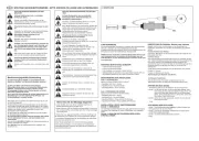
TO ERASE ALL
RECEIVER CODES
1. Pre ss and HOLD
re ce iver or ange
ERASE butt on
6 se co nds . Indica to r
light will t urn ON.
2. Re le ase butt on
whe n light tu rns OFF.
CANADA:
PART NO.: NO. DE PIEZ A:
DATE:
T HE CHAMB ERLAIN
GRO UP, IN C., US A
Ens am blad o e n Méxi co
Ass em bled in Me xico
ELIMINACIÓN DE
TODOS LOS CÓDIGOS DEL
RECEP TOR
1. MANTE NGA PRE SIONADO
e l bo t ón nar anja " ERASE "
de l re ce pto r dura nte 6
se gundo s. La luz de l
indica dor s e e nce nde rá .
2. Sue lte e l bo t ón cua ndo la
luz se apa gue.
DANGER s PELIGRO
132C2280-3D
TO ERASE ALL
RECEIV ER CODE S
1. Press and HOL D
receiver orang e
ERASE b u tto n
6 secon d s. In d icato rlig h t wi ll tu rn ON.
2. Release bu tto n
when lig h t tu rns OF F.
CANADA:
PART NO.: N O. DE PIEZA:
DATE:
THE C H A MB ERLA IN
GROU P, I N C. , U SA
Ensamblado en México
Assembled in Mexico
ELIM INAC IÓN DE
TODOS LOS C ÓDIGOS DEL
RECEP TOR
1. MANTENGAPRE SION ADO
el b o tó n naranja "ERASE "
d el receptor d urante 6 segund o s. L a lu z d el
ind i cado r se encenderá.
2. Suelte el b o t ó n cuand o l a
luz se apagu e.
Before you begin
1
Installation
RECEIVER LOGIC BOARD REPLACEMENT
Model 45ACT
1.2 To maintain your warranty, place the
provided label over the existing label on
the end panel of the garage door opener.
1.1 Remove the light lens by pulling the top
sides of the light lens and rotate the light
lens down. Squeeze the light lens clips to
remove lens from end panel.
NOTE: The products illustrated in the instructions are for reference. Your product may look different.
1.3 Disconnect power to the garage door
opener.
Remove the receiver logic board
2
2.1 Disconnect the wires from the quick-connect terminals ( ). A
Remove the receiver logic board end panel from the garage
door opener.
2.2 Unplug the wire harnesses from the receiver logic
board. You may need needle-nosed pliers, to
remove the harnesses.
2.3 Remove the receiver
logic board from the
end panel by removing
the 2 screws and
releasing the 2 clips.
To prevent possible SERIOUS INJURY or
DEATH:
• Disconnect ALL electric and battery
power BEFORE performing ANY service
or maintenance.
To prevent damage to the receiver/logic
board, DO NOT touch printed circuit board
of replacement receiver/logic board during
installation.
ALWAYS wear protective gloves and eye
protection when changing the battery or
working around the battery compartment.
Screws
Clips
A
To insert or remove
the wires from the
terminal, push in the
tab with a
screwdriver tip.
Red
White
White
Grey
WARNING: This product can expose you to chemicals including lead, which are known to the State of California to cause cancer or birth
defects or other reproductive harm. For more information go to www.P65Warnings.ca.gov