Citronic D1000 Manual
Læs gratis den danske manual til Citronic D1000 (4 sider) i kategorien Modtager. Denne vejledning er vurderet som hjælpsom af 31 personer og har en gennemsnitlig bedømmelse på 4.5 stjerner ud af 16 anmeldelser.
Har du et spørgsmål om Citronic D1000, eller vil du spørge andre brugere om produktet?
Produkt Specifikationer
| Mærke: | Citronic |
| Kategori: | Modtager |
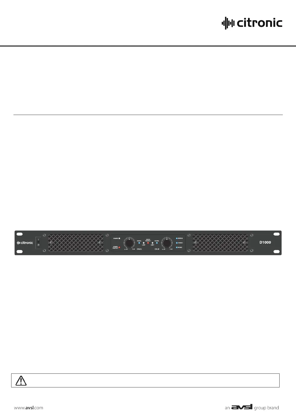
| Model: | D1000 |
| Tænd-/slukkontakt: | Ja |
| Vekselstrømsindgangsspænding: | 220 - 240 V |
| Vekselstrømsindgangsfrekvens: | 50 - 60 Hz |
| Bredde: | 482 mm |
| Dybde: | 245 mm |
| Højde: | 44 mm |
| Vægt: | 3930 g |
| Produktfarve: | Sort |
| Forbindelsesteknologi: | Ledningsført |
| Lyd-output kanaler: | - kanaler |
| Formål: | Optræden/scene |
| klirfaktor (THD): | - % |
| Signal/støjforhold: | - dB |
| Forstærker klasse: | D |
| Spidseffekt pr. kanal: | - W |
| Højttalere tilslutningstype: | XLR |
| XLR udgående: | 1 |
| XLR indgang: | Ja |
| RMS udgangseffekt pr. kanal (4 Ohm): | 500 W |
| RMS udgangseffekt pr. kanal (8 ohm): | 300 W |
| Rackkapacitet: | 1U |
| Indgangsfølsomhed: | 1.44 mV |
| Bridge-mode effekt pr. kanal (8 ohm): | 1000 W |
| Sikringsmærkning: | T10A |
Har du brug for hjælp?
Hvis du har brug for hjælp til Citronic D1000 stil et spørgsmål nedenfor, og andre brugere vil svare dig
Modtager Citronic Manualer


Modtager Manualer
- Vivotek
- iRV Technologies
- Eagle
- Genie
- Camille Bauer
- Godox
- DLS
- Octagon
- Pharos
- Antelope Audio
- Sangean
- Avantree
- Vivolink
- TV Star
- Datapath
Nyeste Modtager Manualer


