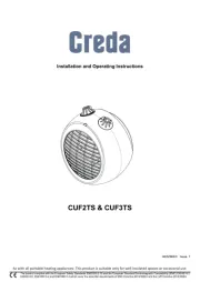
Creda CEP1500E Manual
Creda
Varmeapparat
CEP1500E

| Mærke: | Creda |
| Kategori: | Varmeapparat |
| Model: | CEP1500E |
Har du brug for hjælp?
Hvis du har brug for hjælp til Creda CEP1500E stil et spørgsmål nedenfor, og andre brugere vil svare dig
Varmeapparat Creda Manualer

11 September 2025
11 September 2025
11 September 2025
11 September 2025
10 September 2025
10 September 2025

27 August 2025
26 August 2025

25 August 2025

25 August 2025
Varmeapparat Manualer
- Wilms
- AENO
- Brentwood
- Proline
- G3 Ferrari
- Yellow Garden Line
- Livington
- Heat1
- Gasmate
- Melissa
- Napoleon
- Lervia
- Laica
- Truma
- Blyss
Nyeste Varmeapparat Manualer
29 Oktober 2025
18 Oktober 2025
18 Oktober 2025
18 Oktober 2025
17 Oktober 2025
16 Oktober 2025
15 Oktober 2025
14 Oktober 2025
13 Oktober 2025
12 Oktober 2025